1. Introduction
This manual provides detailed instructions for the installation, operation, and maintenance of your AERO SELFIE 60A 4-in-1 Electronic Speed Controller (ESC). This high-performance ESC is designed for FPV drones, offering reliable control and efficient power management. Please read this manual thoroughly before use to ensure proper setup and safe operation.
2. Safety Guidelines
Adhering to these safety guidelines is crucial for preventing damage to the ESC, your drone, and ensuring personal safety.
- Power Source: Always disconnect the battery before performing any installation, maintenance, or wiring changes.
- Polarity: Ensure correct polarity when connecting the battery. Incorrect connections will cause immediate and irreversible damage.
- Soldering: Use appropriate soldering techniques and equipment. Cold solder joints or solder bridges can lead to malfunctions.
- Insulation: Insulate all exposed solder joints and wires to prevent short circuits.
- Motor Rotation: Verify motor rotation direction before flight. Incorrect rotation can lead to loss of control.
- Environment: Operate the ESC within its specified temperature and humidity ranges.
- Children: Keep electronic components and tools out of reach of children.
3. Package Contents
Verify that all items listed below are included in your package:
- 1 x AERO SELFIE 60A 4-in-1 ESC
- 1 x XT60 Male Power Cable
- 1 x 8pin Cable (1.0mm Pitch, 5cm Length)
- 1 x Fixed Capacitor
- 5 x 3*8mm Silicon Grommets
- 5 x M3 Nuts
- 5 x M3*30 Inner Hexagon Screws

4. Product Overview
4.1 Key Features
- High-Performance: Supports 6V to 28V input voltage (2S-6S LiPo) with 60A continuous current per channel and burst capabilities up to 80A.
- Advanced Control: Equipped with an 8-bit high-speed MCU for precise speed control.
- Efficiency: Features hardware synchronous rectification and regenerative braking for efficient energy recovery.
- Compact Design: Lightweight 13.8g 4-in-1 design for easy integration into FPV drones.
- Reliability: Operates efficiently in temperatures from -10℃ to +55℃ and humidity from 10% to 95%.
- Safety Features: Includes smart throttle signal detection, stalling protection, and motor sound indicators.
- Supported Protocols: Compatible with PWM, DSHOT, and ONESHOT.
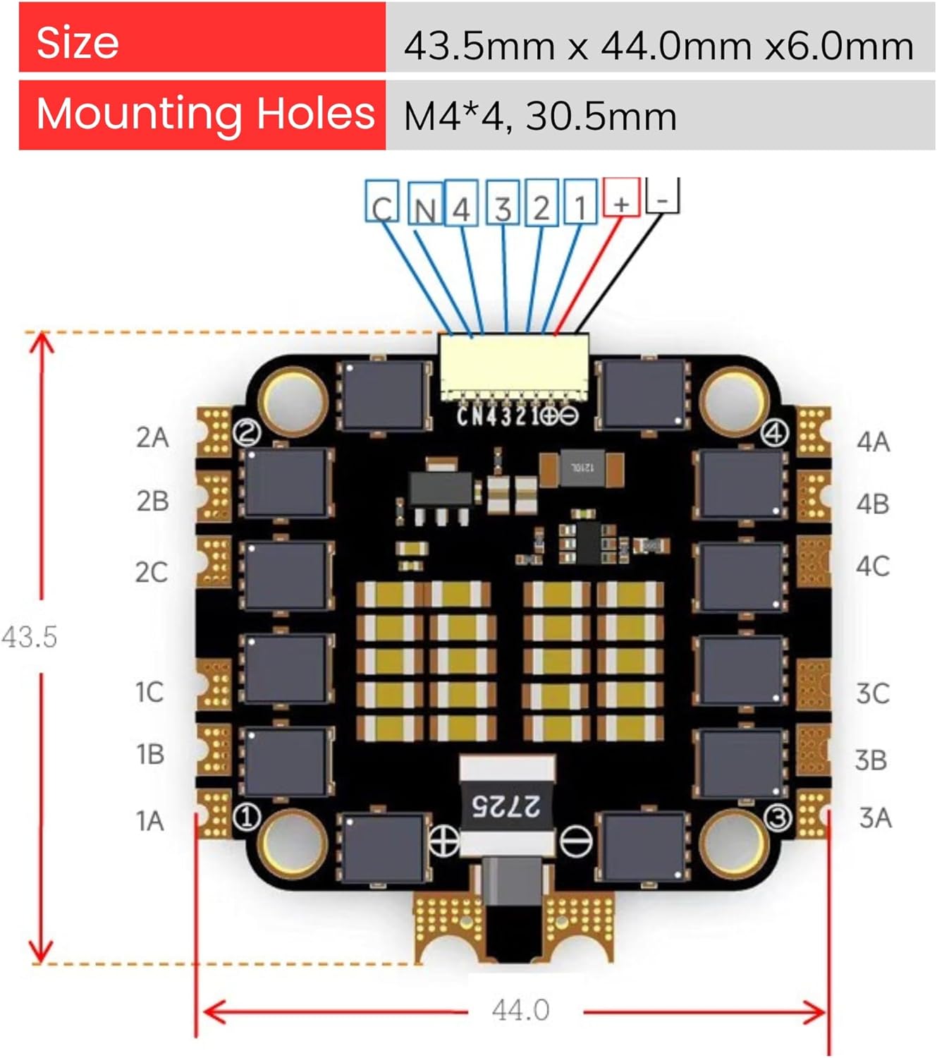
4.2 Physical Dimensions
The AERO SELFIE 60A 4-in-1 ESC has a compact form factor suitable for various drone builds.


5. Specifications
Detailed technical specifications for the AERO SELFIE 60A 4-in-1 ESC:
| Feature | Specification |
|---|---|
| Model Name | 4IN1-ESC-DA1 |
| Input Voltage Range | 6V ~ 28V |
| LiPo Cells Supported | 2S ~ 6S |
| Continuous Current | 60A * 4 channels |
| Peak Current | >80A * 4 |
| MCU | 8-bit High-Speed |
| Drive Signal | PWM, DSHOT, ONESHOT |
| Stalling Protection | Supported |
| Cooling Method | Natural cooling |
| Working Temperature | -10℃ to +55℃ |
| Humidity Range | 10% to 95% |
| Storage Temperature | 0℃ to +25℃ |
| Weight | 13.8 grams |
| Size | 43.5mm x 44.0mm x 6.0mm |
| Mounting Holes | M4*4, 30.5mm spacing |
| BEC Output | None |
| Protection Level | None |
| Hardware Version | 1.0 |
| Software Version | 1.0 |

6. Installation and Wiring
Careful installation and correct wiring are essential for the proper function of your ESC.
6.1 Wiring Diagram
Refer to the diagram below for connecting the ESC to your flight controller, motors, and power source.

- Power Connection (1): Solder the XT60 Male Power Cable to the designated positive (+) and negative (-) pads on the ESC. Ensure correct polarity.
- Fixed Capacitor (3): Solder the included fixed capacitor to the main battery pads (positive to positive, negative to negative) for voltage spike suppression.
- Flight Controller Connection (2): Use the 8-pin cable (1.0mm Pitch) to connect the ESC to your flight controller. Ensure the pinout matches your flight controller's specifications. The cable typically carries battery positive, battery negative, and individual ESC throttle control signals (1#, 2#, 3#, 4#).
- Motor Connections (4): Solder the three wires from each motor to the corresponding motor pads (A, B, C) for each of the four ESC channels. The order of these wires determines motor rotation; this can be adjusted in your flight controller software if needed.
6.2 Mounting
Mount the ESC securely to your drone frame using the provided M3 nuts and M3*30 screws. Utilize the 3*8mm silicon grommets to absorb vibrations and protect the ESC from mechanical stress. Ensure there is adequate airflow around the ESC for natural cooling.
7. Operation
The AERO SELFIE 60A 4-in-1 ESC is designed for straightforward operation once correctly installed and configured.
7.1 Supported Protocols
This ESC supports common digital and analog protocols for communication with your flight controller:
- PWM: Pulse Width Modulation (analog signal).
- DSHOT: Digital Shot (digital signal, DSHOT150, DSHOT300, DSHOT600). DSHOT offers improved noise immunity and faster communication.
- ONESHOT: A faster analog protocol than standard PWM.
Select the appropriate protocol in your flight controller's configuration software (e.g., Betaflight, INAV).
7.2 Advanced Features
- Stalling Protection: The ESC includes features to detect and protect against motor stalling, which can prevent damage to the motors and ESC.
- Motor Sound Indicators: Upon successful initialization, the ESC will emit a series of beeps through the motors, indicating it is ready for arming.
- Regenerative Braking: This feature allows the ESC to recover energy during deceleration, improving efficiency and braking response.
8. Maintenance
To ensure the longevity and optimal performance of your AERO SELFIE ESC, follow these maintenance guidelines:
- Regular Inspection: Periodically check for loose connections, damaged wires, or signs of overheating (discoloration on components).
- Cleaning: Keep the ESC free from dust, dirt, and moisture. Use a soft brush or compressed air for cleaning. Avoid using liquids.
- Storage: Store the ESC in a dry, cool environment, ideally within the recommended storage temperature range of 0℃ to +25℃.
- Firmware Updates: Check the manufacturer's website for any available firmware updates. Follow update instructions carefully.
9. Troubleshooting
If you encounter issues with your AERO SELFIE ESC, consider the following troubleshooting steps:
- No Power/No Initialization Beeps:
- Check battery connection and polarity.
- Inspect power cables (XT60) for damage or poor solder joints.
- Ensure the fixed capacitor is correctly installed and not shorted.
- Verify the 8-pin cable connection to the flight controller is secure and correctly oriented.
- Motors Not Spinning/Irregular Spinning:
- Confirm motor wires are securely soldered to the ESC pads.
- Check for continuity in motor wires.
- Verify ESC protocol settings in your flight controller software match the ESC's capabilities (DSHOT, ONESHOT, PWM).
- Calibrate ESCs if necessary (though DSHOT typically does not require calibration).
- Inspect for any physical obstructions preventing motor rotation.
- ESC Overheating:
- Ensure adequate airflow around the ESC.
- Check for motor issues (e.g., bent shafts, damaged bearings) that could cause excessive current draw.
- Verify propeller size and pitch are appropriate for your motors and battery voltage.
- Voltage Fails to Send Through Connector (as reported by some users):
- If the connector to the flight controller does not supply power, inspect the connector pins for damage or misalignment.
- As an alternative, if your flight controller supports it, you may need to hardwire power directly from the main battery pads on the ESC to the flight controller's power input pads, bypassing the connector for power delivery. Consult your flight controller manual for appropriate power input points.
10. Support Information
For further assistance, technical support, or warranty inquiries, please refer to the official AERO SELFIE website or contact your retailer. Keep your purchase receipt as proof of purchase.
Manufacturer: Shenzhen Ruijie Innovation Technology Co.,Ltd
Brand: AERO SELFIE