D8208-R
Generic D8208-R 8-Port Managed Industrial PoE++ Switch
Model: D8208-R
User Manual
1. Introduction
This user manual provides comprehensive instructions for the installation, configuration, operation, and maintenance of the Generic D8208-R 8-Port Managed Industrial PoE++ Switch. Designed for robust performance in demanding industrial environments, this switch offers advanced Power over Ethernet (PoE++) capabilities and network management features. Please read this manual thoroughly before operating the device to ensure proper usage and to prevent damage.
2. Safety Instructions
- Ensure the power supply voltage matches the device's requirements.
- Do not expose the switch to water, moisture, or extreme temperatures.
- Avoid placing the switch in areas with high vibration or electromagnetic interference.
- Only qualified personnel should perform installation and maintenance.
- Disconnect power before cleaning or servicing the device.
- Proper grounding is essential for safe operation.
3. Package Contents
Verify that all items are present and undamaged upon unpacking:
- Generic D8208-R 8-Port Managed Industrial PoE++ Switch
- Quick Start Guide (if applicable)
- Mounting accessories (e.g., DIN-rail clip, screws)
- Power terminal block
4. Product Overview
The D8208-R is an 8-port managed industrial PoE++ switch designed for robust network connectivity and power delivery in harsh environments. It features a 480W power budget, supporting up to 90W per port, compliant with the IEEE 802.3bt standard.
4.1 Front Panel Layout
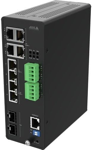
Figure 1: Front and side view of the D8208-R switch, showing various ports and indicators.
This image displays the front and side panels of the D8208-R switch. On the front, you can observe the Ethernet ports, including PoE++ capable ports, and uplink ports. The side panel features ventilation slots. The device is housed in a rugged black casing, indicating its industrial design. Various LED indicators for system status, power, and port activity are also visible.

Figure 2: Angled view of the D8208-R switch, highlighting port details.
This angled view provides a closer look at the connectivity options of the D8208-R switch. It clearly shows the RJ45 Ethernet ports, some labeled for PoE++, and the fiber optic SFP ports for uplink connections. Also visible are the console port (RJ45) for command-line interface access and the removable terminal blocks for power input, emphasizing its industrial application.
4.2 Port Descriptions
- PoE++ Ports (1-8): RJ45 ports supporting IEEE 802.3bt (up to 90W per port) for connecting PoE-powered devices such as IP cameras, wireless access points, and VoIP phones.
- Uplink Ports: SFP slots for fiber optic connections, providing high-speed uplink to the core network.
- Console Port: RJ45 port for local management via a command-line interface (CLI).
- Power Input: Terminal block for redundant DC power input.
4.3 LED Indicators
- SYS: System status indicator (e.g., green for normal operation).
- PWR: Power status indicator.
- ALM: Alarm indicator for system warnings or errors.
- PoE: PoE status for each port.
- Link/Act: Link and activity status for each Ethernet port.
5. Setup
5.1 Mounting the Switch
The D8208-R switch is designed for DIN-rail or wall mounting. Ensure the mounting surface is stable and can support the weight of the switch and connected cables. Leave adequate space around the switch for ventilation and cable management.
- Attach the DIN-rail clip (if not pre-installed) to the rear of the switch using the provided screws.
- Hook the top of the DIN-rail clip onto the DIN rail.
- Push the bottom of the switch towards the DIN rail until it clicks into place.
- For wall mounting, use the provided mounting brackets and screws to secure the switch to a flat surface.
5.2 Power Connection
The switch supports redundant DC power input. Connect the power source to the terminal block on the switch. Observe correct polarity (V+, V-, GND).
- Ensure the power source is turned off before connecting.
- Insert the power wires into the appropriate terminals on the power terminal block.
- Tighten the screws to secure the wires.
- Connect the terminal block to the power input port on the switch.
- Connect the grounding wire to the grounding screw on the switch chassis.
- Turn on the power source. The PWR LED should illuminate.
5.3 Network Connection
Connect network devices and uplink cables to the appropriate ports.
- Connect PoE-powered devices (e.g., IP cameras) to the PoE++ ports (1-8) using standard Ethernet cables.
- Connect uplink cables (Ethernet or SFP transceivers with fiber optic cables) to the uplink ports to connect the switch to your core network.
- The Link/Act LEDs for connected ports should illuminate, indicating a successful connection.
5.4 Initial Configuration (Console)
For initial setup and advanced configuration, connect to the switch via the console port.
- Connect a console cable (RJ45 to DB9 or USB) from your computer to the switch's console port.
- Open a terminal emulation program (e.g., PuTTY, Tera Term) on your computer.
- Configure the serial port settings: Baud Rate: 115200, Data Bits: 8, Parity: None, Stop Bits: 1, Flow Control: None.
- Press Enter to access the command-line interface and log in with default credentials (refer to the Quick Start Guide or manufacturer's documentation for defaults).
6. Operating
6.1 Accessing the Management Interface
The D8208-R is a managed switch, offering configuration via a Web-based Graphical User Interface (GUI) or Command Line Interface (CLI).
- Web GUI: Once the switch has an IP address configured (either statically or via DHCP), open a web browser and enter the switch's IP address. Log in with your credentials.
- CLI: Access via the console port (as described in Section 5.4) or via Telnet/SSH if configured.
6.2 Basic Configuration
Common configurations include:
- IP Address: Assign a static IP address, subnet mask, and gateway for network accessibility.
- VLANs: Create and configure Virtual Local Area Networks to segment network traffic.
- QoS (Quality of Service): Prioritize critical network traffic.
- PoE Settings: Configure PoE power limits, priority, and scheduling for connected devices.
- Rapid Ring Technology: Configure ring topology for network redundancy and high availability.
6.3 PoE++ Device Connection
When connecting PoE++ compatible devices, ensure they comply with IEEE 802.3bt standards. The switch will automatically detect and provide power to compliant devices. Monitor the PoE LEDs to confirm power delivery.
7. Maintenance
7.1 Cleaning
Regular cleaning helps maintain optimal performance and extends the lifespan of the switch.
- Disconnect power before cleaning.
- Use a soft, dry cloth to wipe the exterior of the switch.
- Use compressed air to clear dust from ventilation openings.
- Do not use liquid or aerosol cleaners.
7.2 Firmware Updates
Periodically check the manufacturer's website for firmware updates. Firmware updates can provide new features, performance improvements, and security patches. Follow the instructions provided with the firmware update package carefully.
7.3 Environmental Considerations
Ensure the operating environment remains within the specified temperature and humidity ranges to prevent device malfunction or damage.
8. Troubleshooting
This section provides solutions to common issues you might encounter.
8.1 No Power
- Check if the power cable is securely connected to both the switch and the power source.
- Verify the power source is active and providing the correct voltage.
- Ensure the power terminal block is correctly wired and tightened.
8.2 No Network Connectivity
- Check the Link/Act LEDs on the switch and the connected device. If off, reseat the Ethernet cable or try a different cable.
- Verify that the connected device is powered on and functioning correctly.
- Check network configuration (IP address, subnet mask, gateway) on both the switch and the connected devices.
8.3 PoE Devices Not Receiving Power
- Ensure the connected device is PoE++ (IEEE 802.3bt) compliant.
- Check the PoE LED for the specific port. If off, the device might not be detected or is drawing too much power.
- Verify the total power budget (480W) is not exceeded by all connected PoE devices.
- Check PoE settings in the switch's management interface.
8.4 Resetting the Switch
If issues persist, a factory reset may be necessary. Refer to the specific reset procedure in the full product documentation or contact technical support, as this will erase all configurations.
9. Specifications
Key technical specifications for the Generic D8208-R 8-Port Managed Industrial PoE++ Switch:
- Model Number: D8208-R (Item model number: Z4-02621001)
- Ports: 8-Port Managed Industrial PoE++ Switch
- PoE Standard: IEEE 802.3bt (PoE++)
- Power Budget: 480W total, up to 90W per port
- Management: Managed (Web GUI, CLI)
- Network Resilience: Rapid Ring technology
- Dimensions: 12.89 x 14.76 x 2.12 inches (32.74 x 37.49 x 5.38 cm)
- Weight: 8.62 pounds (3.91 kg)
- Manufacturer: Axis Communications (as per product data)
- Compatible Devices: Cameras and other PoE-powered devices
10. Warranty and Support
For warranty information, technical support, or service inquiries, please refer to the documentation included with your purchase or contact the seller/manufacturer directly. Keep your purchase receipt as proof of purchase for warranty claims.
Ask a question about this manual
Ask about setup, troubleshooting, compatibility, parts, safety, or missing instructions. Manuals+ will review the question and use this page’s manual context to help answer it.