1. Introduction
This manual provides detailed instructions for the installation, operation, and maintenance of your JUTOPIPC H510 Mini-ITX Motherboard. Designed for 10th and 11th Generation Intel Core i3/i5/i7/i9 processors with an LGA1200 socket, this ultra-thin mainboard is suitable for various embedded and industrial PC (IPC) applications, including mini hosts, all-in-one computers, cash registers, and advertising machines.
2. Key Features
- Processor Support: Compatible with 10th/11th Gen Intel Core i3/i5/i7/i9 processors (LGA1200 socket).
- Compact Design: Mini-ITX form factor (17x17cm) for space-constrained applications.
- Memory: Supports DDR4 dual-channel memory (2400/2666/2933/3200 MHz).
- Storage: Features M.2 PCIe 3.0x4 slot (supports SATA/NVMe switching) and two SATA interfaces.
- Connectivity: Dual Gigabit LAN, 2 COM ports (RS232/485 switching), 2 USB 3.0, 2 USB 2.0, HDMI, VGA, LPT, and audio ports.
- Integrated Graphics: Utilizes integrated graphics from 10th and 11th generation Intel Celeron/Pentium Core CPUs.
- Power Input: DC-19V power input (5.5*2.5mm jack).
3. Product Overview and Components
Familiarize yourself with the layout and various components of the H510 Mini-ITX Motherboard.
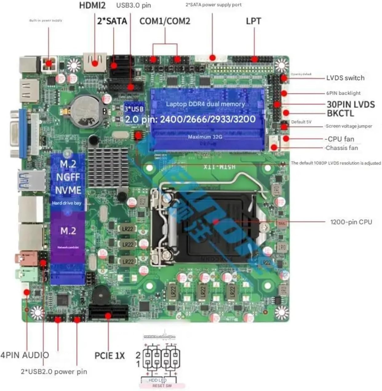
Figure 3.1: Motherboard Component Diagram. This image displays the JUTOPIPC H510 Mini-ITX Motherboard with various components and connectors clearly labeled, including the CPU socket, DDR4 memory slots, M.2 slots, SATA ports, USB headers, and front panel connectors.

Figure 3.2: Rear Input/Output (I/O) Panel. This image provides a close-up view of the rear I/O panel, highlighting the 19V DC power input, HDMI port, VGA port, USB 3.0 ports, dual RJ45 Gigabit LAN ports, and audio jacks (microphone and line-out).
Key Components:
- LGA1200 CPU Socket: For 10th/11th Gen Intel Core processors.
- DDR4 SO-DIMM Slots: Supports laptop DDR4 memory modules.
- M.2 NGFF/NVMe Slot: For high-speed solid-state drives.
- SATA Ports: For traditional SATA hard drives or SSDs.
- PCIe 1X Slot: For expansion cards.
- Rear I/O Ports: Includes HDMI, VGA, USB 3.0, RJ45 Gigabit LAN, Audio (Mic/Line-out), and DC-19V power input.
- Internal Headers: USB 2.0, COM, LPT, Audio, CPU Fan, Chassis Fan, Front Panel.
4. Technical Specifications
Detailed technical specifications for the JUTOPIPC H510 Mini-ITX Motherboard.

Figure 4.1: H510 Motherboard Specifications. This image presents a table detailing the chipset, CPU compatibility, BIOS type, supported operating systems, motherboard size, memory type, hard disk interfaces, network capabilities, video outputs, and various I/O interfaces.
| Feature | Specification |
|---|---|
| Chipset | H510 |
| CPU Socket | LGA1200 |
| Compatible Processors | 10th/11th Gen Intel Core i3/i5/i7/i9, Celeron, Pentium (65W max) |
| Memory Technology | DDR4 SO-DIMM (Laptop DDR4) |
| Memory Speed | 2400/2666/2933/3200 MHz |
| Max Memory Capacity | Up to 32GB (dual channel) |
| Storage Interfaces | 1x M.2 PCIe 3.0x4 (supports SATA/NVMe), 2x SATA III |
| Network | 2x RJ45 Gigabit LAN (Intel 8111 network card chip), M.2 NGFF wireless network card slot |
| Video Output | 1x HDMI, 1x VGA, Internal LVDS 30PIN |
| USB Ports | 2x USB 3.0 (rear), 2x USB 2.0 (internal header) |
| Serial Ports | 2x COM (onboard pins, supports RS232/485 switching) |
| Parallel Port | 1x LPT (onboard) |
| Audio | 1x Microphone, 1x Line-out |
| Expansion Slot | 1x PCIe 1X |
| Power Input | DC 19V (5.5*2.5mm jack, recommended 19V6A or above) |
| Motherboard Size | 17cm x 17cm (Mini-ITX) |
| BIOS | UEFI (PE selects UEFI mode) |
| System Support | Windows 10 64bit, Windows 11 64bit, Ubuntu, Linux |
5. Setup Guide
Follow these steps for proper installation of your H510 Mini-ITX Motherboard and its components.
5.1. CPU Installation
- Carefully open the LGA1200 CPU socket lever.
- Align the CPU (10th/11th Gen Intel Core) with the socket, ensuring the gold triangle on the CPU matches the indicator on the socket.
- Gently place the CPU into the socket without forcing it.
- Close the socket lever to secure the CPU.
- Apply thermal paste and install the CPU cooler according to its manufacturer's instructions.
5.2. RAM Installation
- Locate the DDR4 SO-DIMM slots.
- Open the clips at both ends of the memory slot.
- Align the notch on the DDR4 SO-DIMM module with the key in the slot.
- Insert the module firmly into the slot until the clips snap into place. Ensure both clips are fully engaged.
5.3. Storage Installation
M.2 NVMe/SATA SSD:
- Locate the M.2 slot on the motherboard.
- Insert the M.2 SSD into the slot at an angle.
- Gently push down the SSD and secure it with the provided screw.
SATA Drives:
- Connect one end of a SATA data cable to a SATA port on the motherboard.
- Connect the other end of the SATA data cable to your SATA hard drive or SSD.
- Connect a SATA power cable from your power supply to the SATA drive.
5.4. Power Connection
- Connect the DC-19V power adapter (recommended 19V6A or above) to the DC-IN jack on the rear I/O panel.
- Ensure the power adapter is securely connected.
5.5. Peripheral Connections
- Display: Connect your monitor to the HDMI or VGA port on the rear I/O panel.
- USB Devices: Connect keyboards, mice, and other USB devices to the USB 3.0 ports.
- Network: Connect an Ethernet cable to one of the RJ45 Gigabit LAN ports.
- Audio: Connect speakers or headphones to the Line-out jack and a microphone to the Mic jack.
- Internal Headers: Connect front panel USB, audio, and power/reset switch cables to the corresponding headers on the motherboard. Refer to the motherboard diagram (Figure 3.1) for header locations.
5.6. Chassis Installation
Mount the H510 Mini-ITX motherboard into a compatible Mini-ITX chassis using the appropriate standoffs and screws. Ensure proper airflow within the chassis for optimal cooling.
6. Operating Instructions
6.1. Initial Power On
After all components are installed and connected, connect the power adapter to a power outlet. Press the power button on your chassis to start the system.
6.2. BIOS Setup
To enter the BIOS/UEFI setup utility, press the Del key repeatedly during system startup. In the BIOS, you can configure boot order, system time, and other hardware settings. The H510 uses a UEFI BIOS.
6.3. Operating System Installation
The H510 Mini-ITX Motherboard supports Windows 10 64bit, Windows 11 64bit, Ubuntu, and other Linux distributions. Prepare a bootable USB drive with your preferred operating system and follow the on-screen instructions for installation.
7. Maintenance
- Cleaning: Regularly clean dust from the motherboard and CPU cooler using compressed air. Ensure the system is powered off and unplugged before cleaning.
- Airflow: Ensure adequate airflow within your chassis to prevent overheating. Keep ventilation openings clear.
- BIOS Updates: Check the JUTOPIPC website for any available BIOS updates. Update the BIOS only if necessary and follow the instructions carefully to avoid system damage.
8. Troubleshooting
If you encounter issues with your H510 Mini-ITX Motherboard, consider the following troubleshooting steps:
- No Power: Verify that the DC-19V power adapter is securely connected to both the motherboard and a working power outlet. Check the power button connection to the motherboard.
- No Display: Ensure your monitor is connected to the correct video output (HDMI or VGA) and is powered on. Check that the CPU and RAM are correctly installed.
- System Instability/Crashes: This could indicate issues with RAM, CPU, or power. Re-seat RAM modules. Ensure the CPU cooler is properly installed and making good contact. Check power supply stability.
- Operating System Not Booting: Verify the boot order in BIOS. Ensure your storage drive (M.2 SSD or SATA drive) is correctly installed and detected in BIOS.
- Peripheral Not Detected: Try connecting the peripheral to a different port. Ensure drivers are installed for the operating system.
If problems persist, consult the JUTOPIPC support resources or a qualified technician.
9. Warranty and Support
For warranty information and technical support, please refer to the official JUTOPIPC website or contact your point of purchase. Keep your proof of purchase for warranty claims.