1. Introduction
This manual provides detailed instructions for the installation, operation, and maintenance of the HVAC YELLOW HAT Universal AC Control System Board (Model ACSB-110V). This product is designed as a multifunctional replacement control panel set for air conditioning units operating on 110V-220V systems. Please read this manual thoroughly before installation and use to ensure proper function and safety.

Image 1.1: The Universal AC Control System Board, showing its main components.
2. Product Overview
2.1 Key Features
- 5 Working Modes: Offers versatile operation for various climate control needs.
- 3 Fan Speeds: Adjustable fan speeds for personalized comfort.
- Sleep Function: Optimizes temperature and fan speed for comfortable sleep.
- Accurate and Stable Temperature Control: Ensures consistent and reliable temperature management.
- Universal Voltage Compatibility: Designed for use with 110V-220V AC systems.
2.2 What's in the Box
The package includes the main control board, a remote control, and various accessories necessary for installation.

Image 2.1: All components included in the package, featuring the control board, remote, and various connectors.

Image 2.2: A detailed view of the control board, remote, wiring harness, and various terminal connectors.
3. Safety Information
WARNING: Electrical shock hazard. Installation and servicing should only be performed by qualified personnel. Disconnect power before installing or servicing this product.
- Always ensure the power supply to the air conditioning unit is completely disconnected before attempting any installation or maintenance.
- Verify that the voltage rating of this control board (110V-220V) matches your AC system's requirements.
- Wear appropriate personal protective equipment (PPE), including insulated gloves and safety glasses.
- Do not operate the unit if any part is damaged or if wiring is exposed.
4. Setup and Installation
This universal control system board is designed for split system air conditioners. Careful attention to wiring and connections is crucial for proper operation.
4.1 Pre-Installation Check
- Confirm that the dimensions of the new control board are compatible with the existing space in your AC unit. The board measures approximately 4.33 inches by 4.33 inches.
- Ensure all necessary tools are available, including screwdrivers, wire strippers, and a multimeter for testing.

Image 4.1: The control board with its approximate dimensions (4.33 inches x 4.33 inches) highlighted for compatibility checks.
4.2 Wiring Instructions
Refer to the wiring diagram below for correct connections. It is essential to match the connections accurately to avoid damage to the unit or the control board.

Image 4.2: A comprehensive wiring diagram illustrating connections for the compressor, outdoor fan, indoor unit, and stepper motor. Note the AC 110-220V input.
- Connect the AC 110-220V power supply to the designated terminals (L and N).
- Connect the compressor, outdoor fan, and indoor unit according to the diagram.
- The common pins of the swing socket are 12V output. The common pin of the stepper motor should be inserted into one of the common pins of the swing socket. If the direction of the stepper motor is incorrect, insert the common pin of the stepper motor into another common pin of the swing socket.
- Ensure the room temperature sensor is correctly positioned for accurate readings.
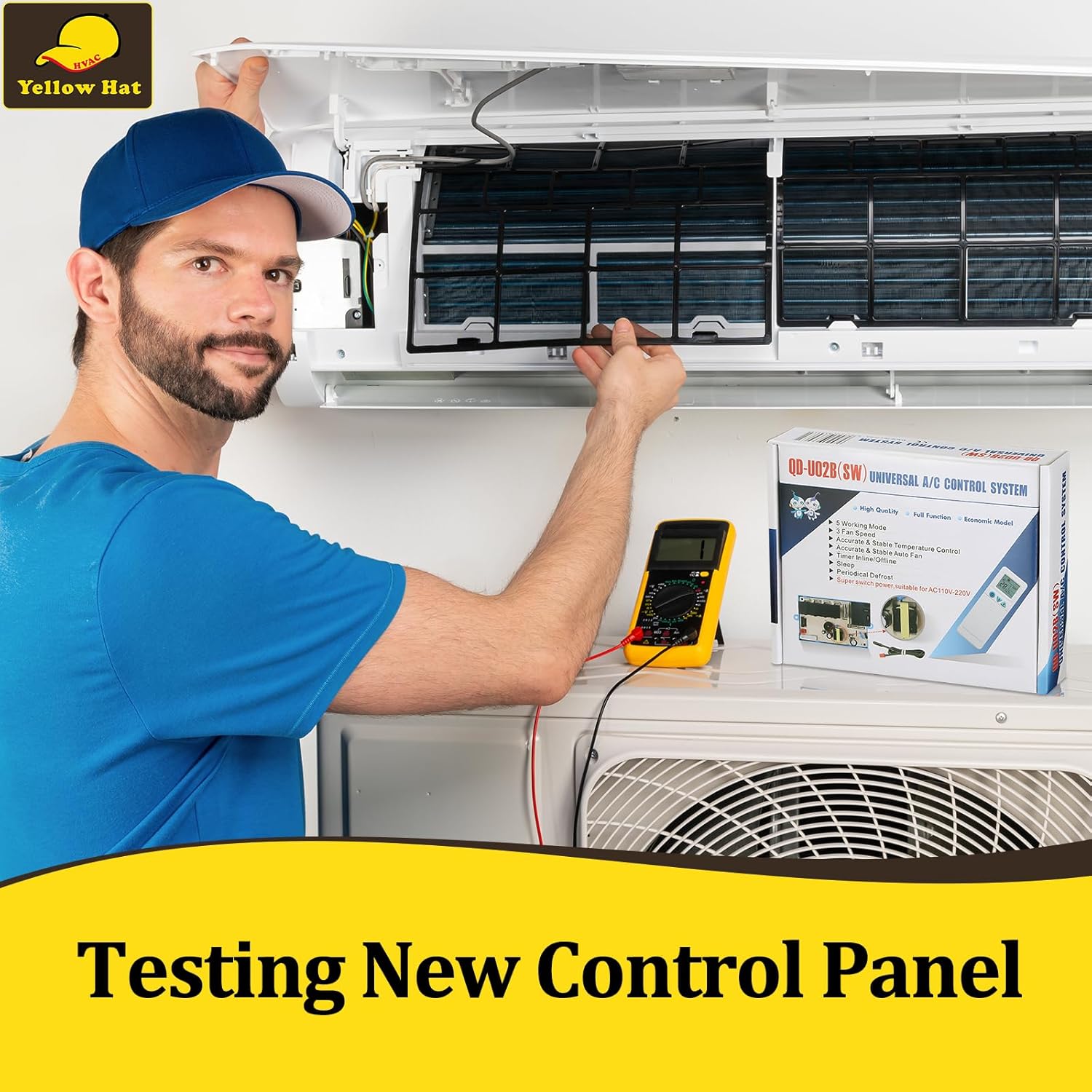
Image 4.3: A technician using a multimeter to test the functionality of a newly installed control panel in an AC unit.
Important: Test the system thoroughly before final assembly and regular use. Avoid strong light in front of the IR receiver to ensure proper remote control functionality.
5. Operating Instructions
The system is operated using the provided remote control. Ensure the remote has working batteries (not included).

Image 5.1: The remote control displaying buttons for Mode, Fan Speed, Swing, Timer, Sleep, and Temperature settings.
5.1 Basic Functions
- Power On/Off: Press the Power button to turn the unit on or off.
- Mode Selection: Press the MODE button to cycle through the 5 available working modes (e.g., Cool, Heat, Fan, Dry, Auto).
- Fan Speed: Use the FAN button to adjust between 3 fan speeds (Low, Medium, High).
- Temperature Adjustment: Use the Temp Up/Down buttons to set the desired temperature.
5.2 Advanced Functions
- Sleep Function: Activate the SLEEP function for optimized comfort and energy saving during sleep.
- Timer Setting: Use the TIMER buttons to set a specific time for the unit to turn on or off.
- Swing Function: Press the SWING button to control the air deflector's movement.
6. Maintenance
Regular maintenance ensures the longevity and efficient operation of your AC control system.
- Cleaning: Periodically clean the remote control with a soft, dry cloth. Do not use liquid cleaners.
- Battery Replacement: Replace remote control batteries when the display dims or the remote becomes unresponsive. Ensure correct polarity.
- System Inspection: During routine AC maintenance, have a qualified technician inspect the control board for any signs of wear or damage.
7. Troubleshooting
If you encounter issues, refer to the following common troubleshooting steps:
| Problem | Possible Cause | Solution |
|---|---|---|
| Unit does not power on. | No power supply; faulty wiring; remote control batteries dead. | Check main power supply; verify wiring connections; replace remote batteries. |
| Remote control unresponsive. | Batteries dead or incorrectly inserted; IR receiver blocked. | Replace batteries; ensure clear line of sight to IR receiver; avoid strong light interference. |
| Incorrect fan direction (stepper motor). | Stepper motor common pin inserted into wrong swing socket pin. | Re-insert the stepper motor common pin into the alternate swing socket common pin. |
| Inaccurate temperature readings. | Temperature sensor improperly placed or faulty. | Ensure sensor is in an optimal location, away from direct drafts or heat sources. |
If problems persist after attempting these solutions, contact a qualified HVAC technician for assistance.
8. Specifications
| Specification | Detail |
|---|---|
| Brand Name | HVAC YELLOW HAT |
| Model Number | ACSB-110V |
| Item Weight | 8.4 ounces |
| Package Dimensions | 6.81 x 5.75 x 1.65 inches |
| Installation Type | Split System |
| Form Factor | Split System |
| Color | Blue |
| Power Source | Corded Electric |
| Control Method | Push Button (on remote) |
| Controller Type | On-Unit Control (board) / Remote Control |
| Voltage Compatibility | 110V-220V |
| Batteries Included? | No |
| Outdoor Unit Required? | No (for the control board itself) |
9. Warranty and Support
For warranty information and technical support, please refer to the documentation provided with your purchase or contact HVAC YELLOW HAT customer service directly. Keep your purchase receipt as proof of purchase.
HVAC YELLOW HAT Contact Information: Please visit the official HVAC YELLOW HAT store on Amazon for the most up-to-date support information: HVAC YELLOW HAT Store