Introduction
This manual provides detailed instructions for the installation, operation, and maintenance of your LSLSL Liquid Level Sensor and Water Level Gauge. This integrated system is designed for accurate measurement and display of liquid levels in various applications, including fuel and water tanks in engines, ships, construction machinery, agricultural machinery, and automotive modifications.

Figure 1: LSLSL Liquid Level Sensor and Water Level Gauge Kit.
Key Features
- Compatible with both Diesel and Gasoline Engines.
- Suitable for both Fuel Level Gauge and Water Level Gauge applications.
- Features a secure snap-together harness connector for robust and firm connection, ensuring reliable operation even in strong vibrations.
- Versatile application across engines, generating units, ships, construction machinery, agricultural machinery, and automotive modifications.
- Gauge features curved glass with anti-fog function for clear readability.
- Gauge includes 8-color backlight options for enhanced visibility in various lighting conditions.
Package Contents
Please verify that all items listed below are included in your package:
- 1 x 52mm Water Level Gauge
- 1 x Liquid Level Sensor (400MM length, 0-190 Ohm output)
- 1 x Gasket
- 5 x M5 Screws

Figure 2: Included sensor components: sensor, gasket, and screws.
Specifications
Sensor Specifications:
- Protection Rating: IP67
- Resolution Range: 21 mm
- Assembly: SAE standard 5 holes
- Rated Current for Alarm Switch: 500mA
- Operating Temperatures: -40 to 85 Celsius
- Sensor Length: 400MM (This model) - available 100MM~1500MM
- Mounting: 5 pieces of M5 screws and 2 mm thick gasket
- Output Signal: 0~190 ohm
Gauge Specifications:
- Input Signal: R ohm (0-190 Ohm compatible)
- Indication Range: E-F (Empty to Full)
- Working Current: ≤ 60mA
- Install Diameter: 52mm
- Storage Temperature: -40~+85 Celsius
- Operating Temperature: -30~+75 Celsius
- Water Level Gauge Waterproof Rating: Front cover IP67, Back cover IP5
- Backlight Colors: 8 colors (red, green, blue, white, yellow, olivine, orange, purple)

Figure 3: Detailed dimensions and technical drawing of the sensor.
Setup and Installation
Sensor Installation:
- Ensure the tank is empty or at a safe level before installation.
- Identify the appropriate mounting location on your tank, typically a standard SAE 5-hole pattern.
- Place the provided gasket onto the sensor's mounting flange.
- Insert the sensor into the tank opening, aligning the holes.
- Secure the sensor using the 5 M5 screws provided, tightening them evenly to ensure a watertight seal.
Wiring Connection:
Proper wiring is crucial for accurate operation. Refer to the diagram below and the following instructions:
- Blue wire (Sensor): Connect to the ground wire of your electrical system.
- Brown wire (Sensor): Connect to the signal input wire of the water level gauge.
- Gauge Connections:
- Red wire: Connect to Battery Positive (+9-32VDC).
- Black wire: Connect to Battery Negative (-).
- Orange wire: Connect to Backlight Positive (+9-32VDC).
- Sensor Signal Input: Connect to the brown wire from the sensor.
Important Note: 0~190 ohm sensors must only be used with 0~190 ohm fuel/water gauges for correct readings.

Figure 4: Rear view of the gauge with connection points labeled.
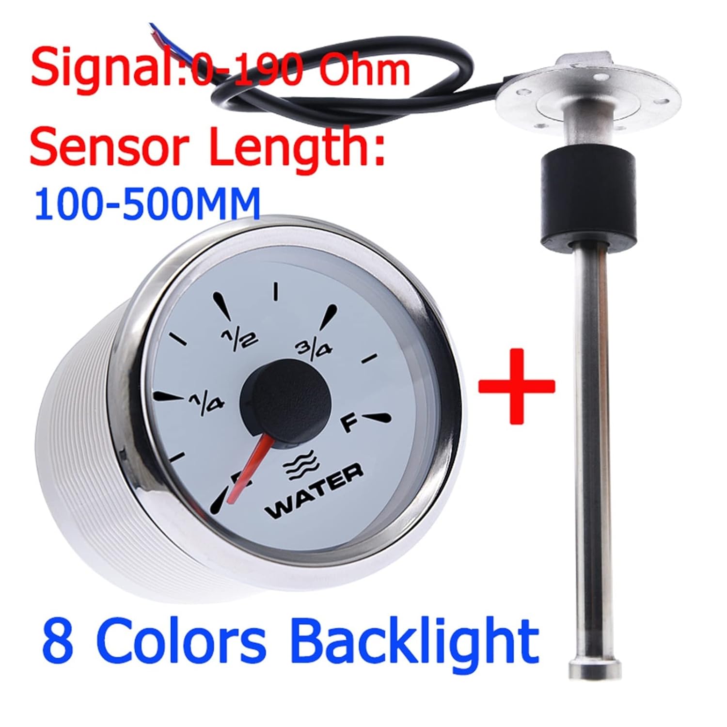
Figure 5: Overview of sensor signal (0-190 Ohm) and length range.
Operation
Reading the Gauge:
Once properly installed and powered, the gauge will display the liquid level in your tank. The needle will move between 'E' (Empty) and 'F' (Full) indicating the current level. A resistance of 0 Ohm from the sensor corresponds to an empty tank, while 190 Ohm corresponds to a full tank.
Backlight Function:
The gauge features an 8-color backlight. The backlight color can typically be cycled or set via a button on the back of the gauge (refer to Figure 4, 'Mode' button) or through specific wiring configurations, depending on the exact model. This allows for optimal visibility in various lighting conditions.

Figure 6: Examples of the 8-color backlight options on the gauge.

Figure 7: Close-up view of the gauge displaying an orange backlight.
Maintenance
- Cleaning: Periodically wipe the gauge's front cover with a soft, damp cloth. Avoid abrasive cleaners or solvents.
- Connections: Regularly inspect all wiring connections for corrosion or looseness. Ensure the snap-together harness connector remains firmly seated.
- Sensor Inspection: If accessible, periodically check the sensor for any physical damage or accumulation of debris that might affect its float mechanism.
- Seal Integrity: Verify the integrity of the gasket and mounting screws to prevent leaks, especially after prolonged use or exposure to harsh conditions.
Troubleshooting
| Problem | Possible Cause | Solution |
|---|---|---|
| Gauge not powering on / No backlight | No power supply; Loose wiring; Blown fuse. | Check power connections to the gauge (Red and Black wires). Ensure fuse is intact. Verify Orange wire for backlight power. |
| Gauge reads 'E' (Empty) constantly | Sensor not connected; Sensor faulty; Open circuit in signal wire. | Check brown wire connection from sensor to gauge. Inspect sensor wiring for breaks. Test sensor resistance (0 Ohm when empty, 190 Ohm when full). |
| Gauge reads 'F' (Full) constantly | Short circuit in signal wire; Sensor faulty. | Check brown wire for short circuits. Test sensor resistance. |
| Inaccurate readings | Incorrect sensor resistance range; Sensor float obstructed; Loose connections. | Ensure sensor is 0-190 Ohm type. Check for obstructions around the sensor float. Verify all wiring connections are secure. |
Support and Warranty
For technical assistance, troubleshooting beyond this guide, or warranty inquiries, please contact your retailer or the manufacturer, LSLSL. Please have your product model number (3256803121630118) and purchase information ready when contacting support.
This product is manufactured by LSLSL and is subject to their standard warranty terms and conditions. Please refer to your purchase documentation for specific warranty details.