1. Introduction and Overview
This manual provides comprehensive instructions for the installation, operation, and maintenance of the CVXDD Digital FlowMeter and Ultrasonic Heat Meter. This device is designed for precise measurement of flow rate and heat energy in various applications, including air conditioning systems, heating systems, and general engineering water metering. Its robust design ensures high stability and convenient operation.
The meter features a digital display combined with a pointer wheel for clear and convenient readings, offering high accuracy and reliability for industrial and commercial use.
2. Product Features
- Clear Display: Utilizes a pointer wheel combination display with a digital readout for easy and accurate data interpretation.
- High Performance: Offers large flow capacity and minimal pressure loss, ensuring stable transmission performance.
- Durable Construction: Features a robust cover design for enhanced durability and ease of use, with good cooling performance.
- Versatile Application: Widely applicable in various settings, including hotel properties and other industrial environments.
- Corrosion Resistance: Exhibits good resistance to acid and alkali corrosion, extending product lifespan.
3. Specifications
| Specification | Value |
|---|---|
| DIY Supplies | ELECTRICAL |
| Minimum Flow Rate | 0.2 m³/h |
| Power Supply Method | Battery with external power supply |
| Main Material | Aluminium |
| Protection Level | IP54 |
| Manufacturer | CVXDD |
| Part Number | 260554115 |
| Item Weight | 1.76 pounds |
| Package Dimensions | 9.06 x 5.91 x 3.94 inches |
| Country of Origin | China |
| Model Number | 260554115 |
| Size (Current Variant) | A |
| Color (Current Variant) | Dn32 |
| Item Package Quantity | 1 |
| Number Of Pieces | 1 |
| Date First Available | December 10, 2024 |
4. Setup and Installation
Proper installation is crucial for the accurate and reliable operation of your Digital FlowMeter. Please follow these steps carefully.
4.1 Unpacking and Inspection
Carefully remove the meter from its packaging. Inspect all components for any signs of damage during transit. Ensure all parts listed in the packing list are present.
4.2 Mounting the Meter
The meter can be installed horizontally or vertically. Ensure the flow direction arrow on the meter body aligns with the actual fluid flow in the pipe. The meter should be installed in a section of pipe that is free from turbulence and vibrations.

Figure 4.1: Bottom view of the meter, illustrating the threaded pipe connections for integration into a fluid system. Note the robust brass construction.
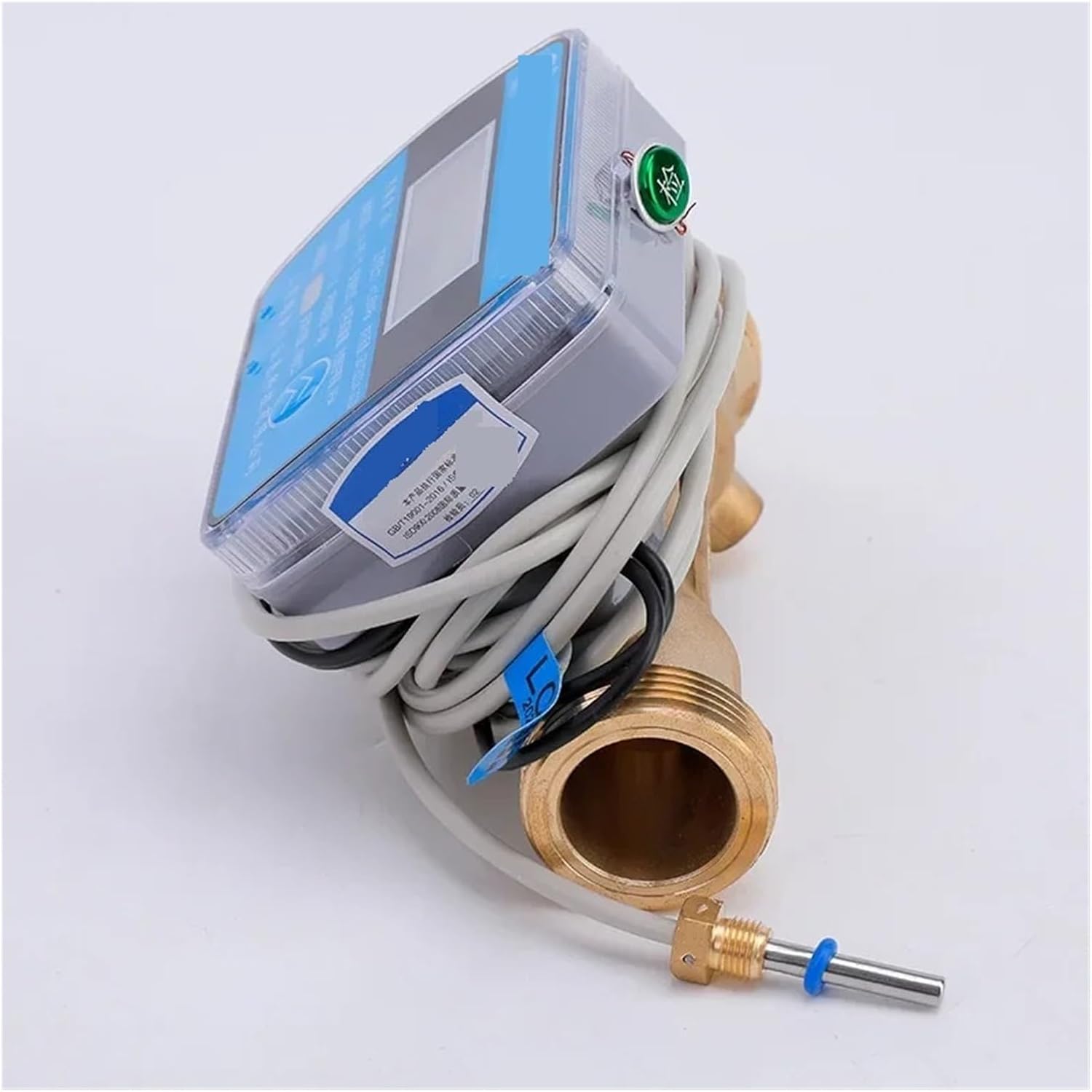
Figure 4.2: Side view of the meter, showing the integrated wiring and the PT1000 temperature sensor, which is essential for heat energy calculation.
4.3 Electrical Connections
The meter operates on battery power with an option for external power supply. Connect the necessary power cables according to local electrical codes and the meter's specifications. Ensure all connections are secure and properly insulated to maintain the IP54 protection level.
Connect the temperature sensors (if applicable for heat metering) to the designated ports. The PT1000 sensor shown in Figure 4.2 is crucial for accurate heat energy measurement.

Figure 4.3: Front view of the meter, displaying the digital readout and the various wiring connections for power and sensors.

Figure 4.4: Angled view highlighting the meter's display and the connection points for the flow and temperature sensors.
4.4 System Integration
Once physically installed and wired, integrate the meter into your existing system. Ensure proper sealing of all pipe connections to prevent leaks. Verify that the meter is receiving adequate power and that all sensors are correctly recognized by the unit.
5. Operating Instructions
The Digital FlowMeter is designed for straightforward operation. Follow these guidelines to ensure accurate readings and optimal performance.
5.1 Powering On/Off
The meter typically powers on automatically when connected to an external power source or when the internal battery is active. There may be a power button or switch on the unit; refer to the specific markings on your device. To power off, disconnect the external power and allow the internal battery to deplete, or use the designated power switch if available.
5.2 Reading the Display
The meter features a combination of a digital display and a pointer wheel for reading measurements. The digital display provides precise numerical values for flow rate, accumulated volume, and heat energy (if applicable). The pointer wheel offers a visual indication and can be used for quick checks or as a backup.
- Digital Readout: Displays current flow rate (e.g., m³/h), total accumulated volume (e.g., m³), and heat energy (e.g., kWh or GJ).
- Pointer Wheel: Provides a mechanical counter for accumulated volume, typically in cubic meters.
Pressing any buttons on the meter (if present) may cycle through different display modes, showing various parameters such as instantaneous flow, total flow, temperature, and heat consumption. Consult the labels on the meter for button functions.
5.3 Data Logging and Output (If Applicable)
Some models may include data logging capabilities or output ports for connecting to external systems. Refer to the specific model's advanced features for details on data retrieval or integration with building management systems.
6. Maintenance
Regular maintenance ensures the longevity and accuracy of your Digital FlowMeter. The meter is designed for low maintenance, but periodic checks are recommended.
6.1 Cleaning
Wipe the exterior of the meter with a soft, damp cloth. Do not use abrasive cleaners or solvents, as these can damage the casing or display. Ensure the display remains clear for easy reading.
6.2 Battery Replacement
If the meter is primarily battery-powered, monitor the battery indicator (if available). Replace batteries as needed, following the instructions on the meter's casing or in a separate battery replacement guide. Ensure the correct battery type is used.
6.3 Connection Checks
Periodically inspect all pipe connections for leaks and electrical connections for corrosion or looseness. Tighten any loose connections to maintain optimal performance and safety.
6.4 Environmental Considerations
While the meter has an IP54 protection level, it is recommended to protect it from extreme temperatures, direct sunlight, and excessive moisture to prolong its lifespan. The meter's material offers good resistance to acid and alkali corrosion, making it suitable for various industrial environments.
7. Troubleshooting
This section provides solutions to common issues you might encounter with your Digital FlowMeter. If the problem persists, contact customer support.
7.1 No Display / Blank Screen
- Check Power: Ensure the external power supply is connected and functioning, or that the internal battery is charged and correctly installed.
- Power Button: Verify if the meter has a power button and if it is in the 'On' position.
- Connections: Inspect all electrical connections for looseness or damage.
7.2 Inaccurate Readings
- Flow Direction: Confirm that the meter is installed with the correct flow direction as indicated by the arrow on the meter body.
- Air Bubbles: Large air bubbles in the fluid can affect accuracy. Ensure the system is properly purged of air.
- Sensor Connections: For heat meters, ensure temperature sensors are correctly installed and connected.
- Turbulence: Ensure the meter is installed in a straight section of pipe, away from elbows, valves, or pumps that could cause turbulence.
7.3 Leaks at Connections
- Tighten Connections: Gently tighten pipe connections. Do not overtighten, as this can damage threads.
- Sealing Material: Ensure appropriate sealing tape (e.g., PTFE tape) or sealant was used during installation.
- Inspect Threads: Check for any damage to the meter's threads or the pipe threads.
8. Warranty and Support
For specific warranty terms and conditions, please refer to the documentation provided at the time of purchase or contact the seller directly. Warranty coverage typically includes defects in materials and workmanship under normal use.
For technical support, troubleshooting assistance beyond this manual, or to inquire about replacement parts, please contact CVXDD customer service or your authorized distributor. Have your product model number (DN32, 260554115) and purchase details ready when contacting support.
Manufacturer: CVXDD
Model: DN32 (260554115)