Joinfworld B0DPY9SMVK
Joinfworld Sump Pump Water Alarm Control Panel
Model: B0DPY9SMVK - Instruction Manual
1. Introduction
The Joinfworld Sump Pump Water Alarm Control Panel is designed to provide proactive flood protection by detecting elevated water levels in various applications such as sewage pits, septic tanks, basements, water tanks, and lift stations. This system features a robust, weather-resistant casing, an AC contactor for enhanced safety, and an independent circuit for reliable operation. It includes a flash light and a 110dB alarm to alert users to potential water issues.
2. Safety Information
- Electrical Safety: Ensure all power is disconnected before installation or maintenance. Installation should be performed by a qualified electrician in accordance with local electrical codes.
- Water Exposure: While the unit is waterproof, avoid submerging the control panel. Ensure all connections are sealed to prevent water ingress.
- Alarm Volume: The alarm is 110dB loud. Avoid prolonged exposure to the alarm sound at close range to prevent hearing damage.
- Proper Mounting: Mount the control panel securely on a stable surface to prevent accidental dislodgement.
3. Product Overview
The Joinfworld Sump Pump Water Alarm Control Panel integrates several components to ensure reliable water level monitoring and pump control.
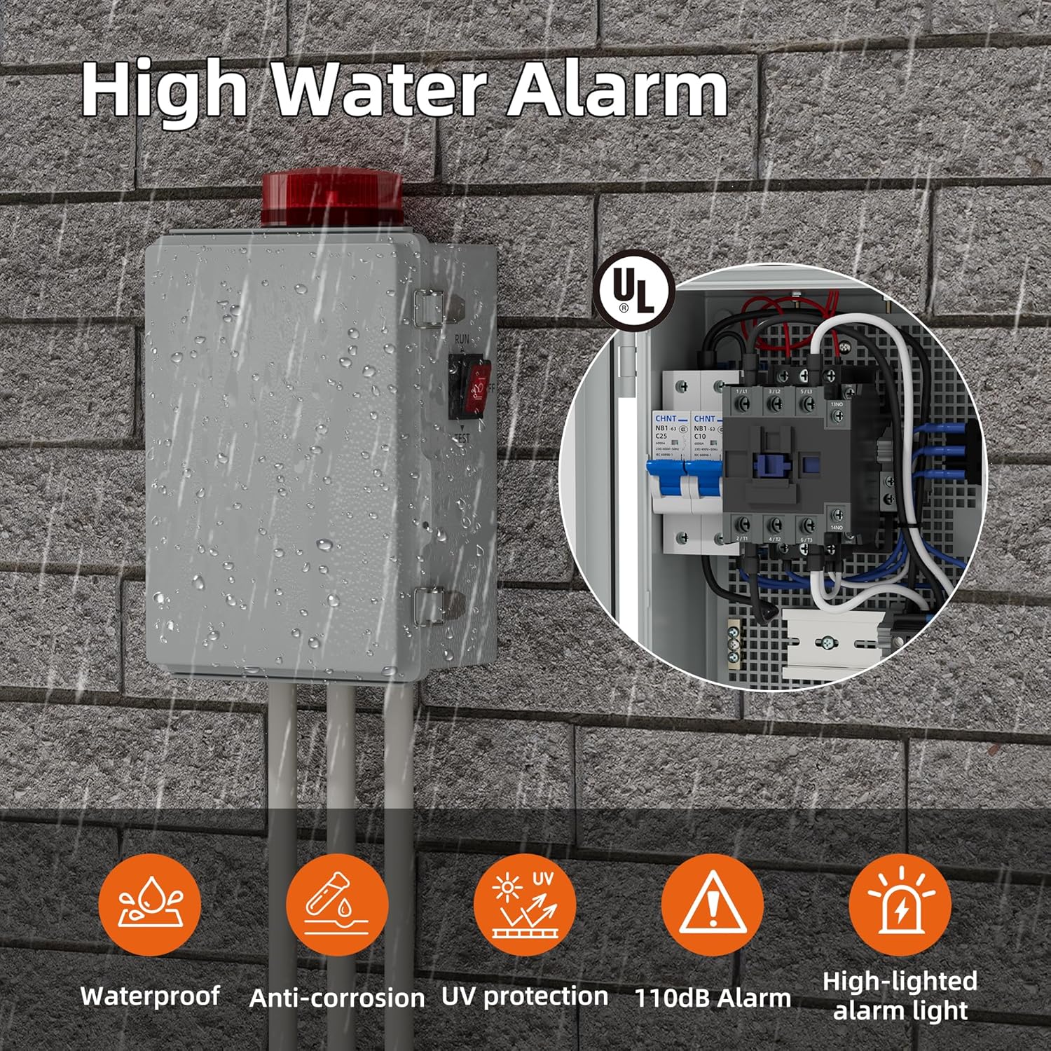
Figure 1: Joinfworld Sump Pump Water Alarm Control Panel. This image shows the control panel mounted on a brick wall, demonstrating its waterproof design and key features like the 110dB alarm and high-lighted alarm light.
Key Features:
- Safe & Reliable: Equipped with an AC contactor for enhanced safety and reliable performance. Robust, weather-resistant casing for various environmental conditions.
- Proactive Flood Protection: Detects water levels in sewage pits or septic tanks, providing protection against potential flood threats.
- Independent Circuit: Allows the alarm and pump to be controlled separately, preventing damage in case of device failure.
- Powerful and Secure: Additional AC contactor protects the pump and circuit. Overall operating power of 2.75 kW.
- Wide Application: Suitable for monitoring sewage pumps, water tanks, lift stations, low-density oil, and wastewater.
Internal Components:

Figure 2: Internal components of the control panel. This image details the circuit breaker, alternating current contactor, terminal block, grounding bar, and the alarm light.
- Circuit Breaker: Provides overcurrent protection for the system.
- Alternating Current Contactor: Manages the power supply to the pump, ensuring safe and controlled operation.
- Terminal Block: Facilitates secure and organized wiring connections.
- Grounding Bar: Ensures proper grounding for electrical safety.
- Alarm Light: Visual indicator for high water level alerts.
4. Setup and Installation
Careful installation is crucial for the proper functioning of your water alarm system. Follow these steps for setup:
4.1 Mounting the Control Panel
- Select a suitable location for the control panel, ensuring it is easily accessible for monitoring and maintenance, yet protected from direct impact.
- Use appropriate fasteners to securely mount the weather-resistant casing to a wall or stable structure.
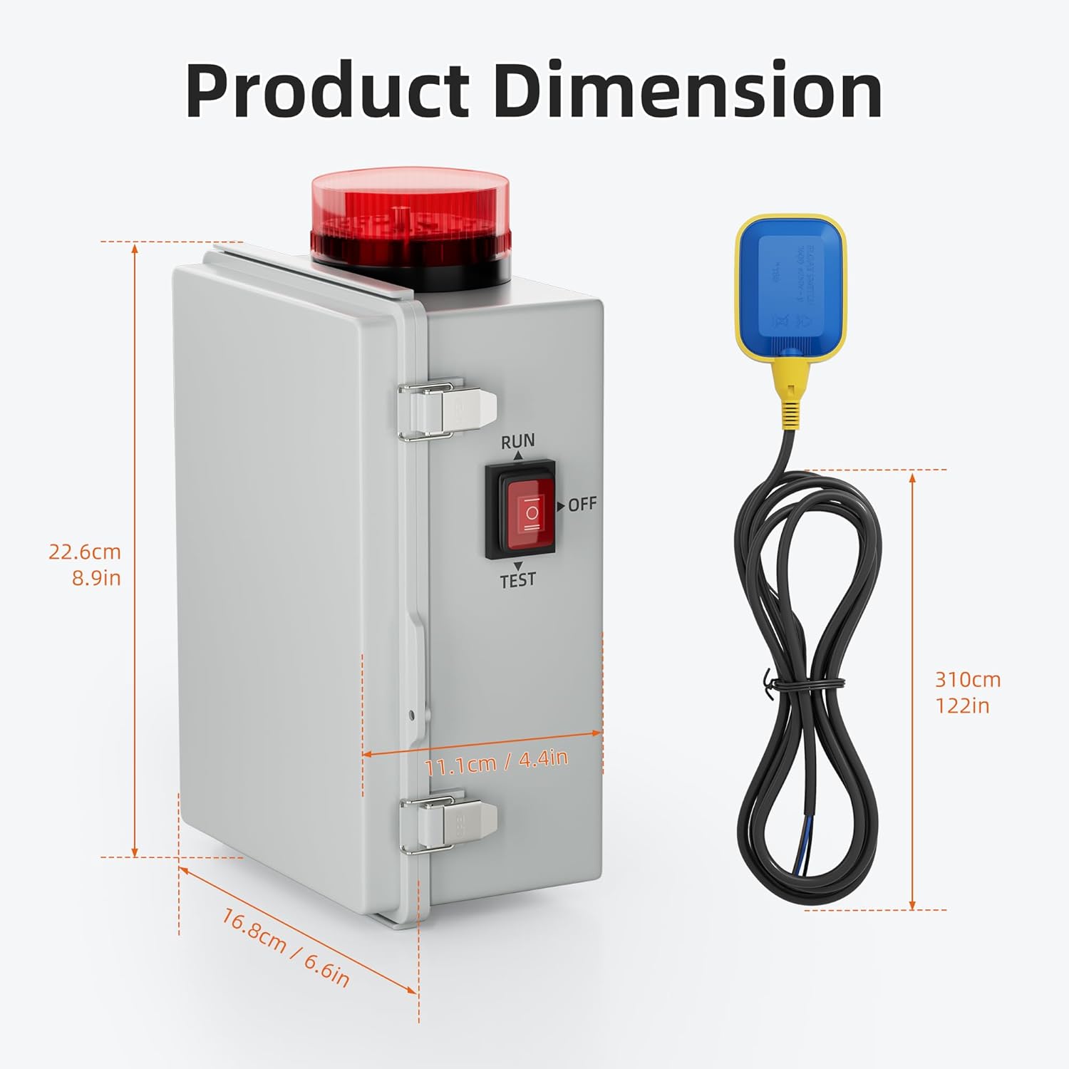
Figure 3: Product Dimensions. Refer to this diagram for precise measurements of the control panel and the float switch cable length for installation planning.
4.2 Wiring Connections
Connect the float switch and the pump to the terminal block inside the control panel. Ensure all connections are tight and secure. Refer to the internal component diagram (Figure 2) for terminal locations.
- Float Switch: Connect the float switch wires to the designated terminals. The float switch detects water levels and triggers the alarm/pump based on its position.
- Pump: Connect the sump pump's power wires to the pump output terminals. The AC contactor will control the power to the pump.
- Power Supply: Connect the main power supply to the control panel's input terminals. Ensure the voltage matches the product specifications (e.g., 120V AC).
- Grounding: Connect the system to a proper ground using the grounding bar for safety.
Note: Some units may have the 'Run' and 'Test' switch installed in a reversed position. Verify the switch functionality during initial testing and adjust if necessary.
5. Operating Modes
The control panel offers different operating modes to suit various application needs. The main switch on the panel allows selection between 'RUN', 'OFF', and 'TEST' positions.

Figure 4: Working Modes. This diagram illustrates the three primary operational modes of the control panel.
5.1 Mode 1: Alarm Only
- In this mode, the alarm operates automatically when high water is detected by the float switch.
- Turning off the alarm and turning on the pump requires manual operation. The pump will not activate automatically.
5.2 Mode 2: Manual Pump Control
- When high water is detected, the alarm will activate.
- The pump will not start automatically. Manual intervention is required to activate the pump to remove water.
5.3 Mode 3: Automatic Pump Control
- This mode provides fully automatic operation. When the float switch detects a high water level, the alarm will sound, and the pump will automatically turn on to remove the water.
- Once the water level drops and the float switch disengages, the pump will automatically turn off, and the alarm will cease.
5.4 Test Mode
- The 'TEST' position on the main switch allows you to verify the alarm and pump functionality without actual high water conditions.
- When in 'TEST' mode, the alarm will activate, and the pump will run, regardless of the float switch position. This is useful for periodic checks.
6. Maintenance
Regular maintenance ensures the longevity and reliability of your Joinfworld Sump Pump Water Alarm Control Panel.
- Periodic Testing: Regularly use the 'TEST' mode to ensure the alarm and pump activate correctly. This should be done at least once every three months.
- Clean Float Switch: Inspect the float switch for any debris or buildup that might impede its movement. Clean as necessary.
- Inspect Wiring: Periodically check all wiring connections for tightness and signs of wear or corrosion.
- Casing Integrity: Ensure the weather-resistant casing remains sealed and free from cracks or damage to protect internal components from environmental elements.
- Battery Check (if applicable): If your model includes a backup battery, check its charge and replace it as recommended by the manufacturer.
7. Troubleshooting
If you encounter issues with your water alarm system, refer to the following troubleshooting guide:
| Problem | Possible Cause | Solution |
|---|---|---|
| Alarm does not sound / Light does not flash | No power to unit; Float switch stuck or faulty; Alarm component failure. | Check power supply and circuit breaker. Inspect float switch for obstructions. Test alarm in 'TEST' mode. |
| Pump does not activate in automatic mode | Float switch faulty or incorrectly wired; Pump failure; Control panel in incorrect mode. | Verify float switch operation and wiring. Check pump for functionality. Ensure control panel is in 'Mode 3' (Automatic Pump Control). |
| Alarm sounds continuously / Pump runs continuously | Float switch stuck in 'up' position; Continuous high water level; Wiring error. | Inspect float switch for obstructions. Address the source of continuous high water. Check wiring for correct connections. |
| Switch 'Run' and 'Test' functions are reversed | Manufacturing error in switch installation. | If comfortable and qualified, carefully reverse the switch wiring internally. Otherwise, contact support. |
8. Specifications
| Specification | Value |
|---|---|
| Brand | Joinfworld |
| Product Dimensions (L x W x H) | 4.53" x 7.56" x 12.6" |
| Control Method | Push Button |
| Noise Level (Audible Noise) | 110 Decibels |
| Mounting Type | Ceiling Mount (Note: This may refer to the float switch or general mounting, verify with product diagram) |
| Sensor Technology | Contact Sensor (Float Switch) |
| Item Weight | 1.9 Kilograms |
| Unit Count | 1.0 Count |
| Built-In Media | Water alarm |
9. Warranty and Support
For warranty information and customer support, please refer to the documentation included with your purchase or contact Joinfworld directly through their official website or customer service channels. Keep your purchase receipt as proof of purchase.
Ask a question about this manual
Ask about setup, troubleshooting, compatibility, parts, safety, or missing instructions. Manuals+ will review the question and use this page’s manual context to help answer it.