Srliya Srliyasfawm6u1gi
BSIDE Digital Multimeter S10 User Manual
Model: Srliyasfawm6u1gi | Brand: Srliya
Introduction
This user manual provides detailed instructions for the safe and effective operation of your BSIDE Digital Multimeter S10. This smart color LCD display multimeter offers 9999 counts and is designed for accurate voltage testing and various electrical measurements. Please read this manual thoroughly before use and retain it for future reference.

The BSIDE Digital Multimeter S10 is a compact and intelligent device featuring a color LCD display for enhanced readability. It comes with a pair of red and black test leads for various electrical measurements. The device is designed for ease of use with automatic identification of measurement parameters.
Safety Information
Always observe the following safety precautions to prevent personal injury and damage to the multimeter or equipment under test.
- Caution: When measuring high voltage, operate with extreme caution to avoid electric shock.
- Do not use the multimeter if it appears damaged or if the test leads are damaged.
- Do not apply more than the rated voltage, as marked on the multimeter, between the terminals or between any terminal and earth ground.
- Use the proper terminals, function, and range for your measurements.
- Do not operate the multimeter around explosive gas, vapor, or dust.
- Always disconnect power to the circuit and discharge all high-voltage capacitors before testing resistance, continuity, diodes, or capacitance.
- Replace the batteries as soon as the low battery indicator appears.
Package Contents
Verify that all items listed below are included in your package. If any items are missing or damaged, please contact your retailer.
- 1 x Digital Multimeter (BSIDE S10)
- 1 x User Manual
- 2 x Test Pens (Test Leads)

The package includes the main multimeter unit and a set of red and black test leads, essential for conducting electrical measurements. A user manual is also provided for detailed operational guidance.
Product Overview
Familiarize yourself with the components of your BSIDE Digital Multimeter S10.
The multimeter features a prominent color LCD display that shows measurement values, units, and other indicators. The display is designed for clarity, even in varying light conditions. Below the display are the input jacks for connecting the test leads.
- Color LCD Display: High-resolution screen displaying 9999 counts, polarity indication, and various measurement parameters.
- Power Button: Located on the top right, used to turn the device on/off.
- FUNC Button: Used to switch between functions in manual mode (if applicable).
- COM Jack: Common input terminal for the black test lead.
- INPUT Jack: Input terminal for the red test lead for most measurements.
Setup
Battery Installation
The multimeter requires 2 x 1.5V AAA batteries (not included) for operation.
- Locate the battery compartment cover on the back of the multimeter.
- Use a screwdriver to open the battery compartment.
- Insert two 1.5V AAA batteries, ensuring correct polarity (+ and -).
- Replace the battery compartment cover and secure it with the screw.

This image shows the open battery compartment on the back of the multimeter, designed to hold two AAA batteries. Proper battery insertion is crucial for the device's functionality.
Connecting Test Leads
Connect the test leads to the appropriate input jacks on the multimeter.
- Insert the black test lead into the "COM" (Common) jack.
- Insert the red test lead into the "INPUT" jack for most measurements (voltage, resistance, capacitance, diode, continuity, frequency, duty cycle).

The multimeter is shown with the red and black test leads properly connected to their respective input jacks, ready for measurement. The red lead is in the INPUT jack and the black lead is in the COM jack.
Operating Instructions
The BSIDE S10 features an intelligent auto mode that simplifies most measurements. For specific functions, manual selection may be required using the FUNC button.
Power On/Off
- Press the power button (located on the top right) to turn the multimeter on.
- The device will automatically shut down after 5 minutes of inactivity to conserve battery life.
- To manually turn off, press and hold the power button.
Auto Mode Operation
In Auto Mode, the multimeter automatically identifies the type of measurement (AC voltage, DC voltage, resistance, continuity) and selects the appropriate range.
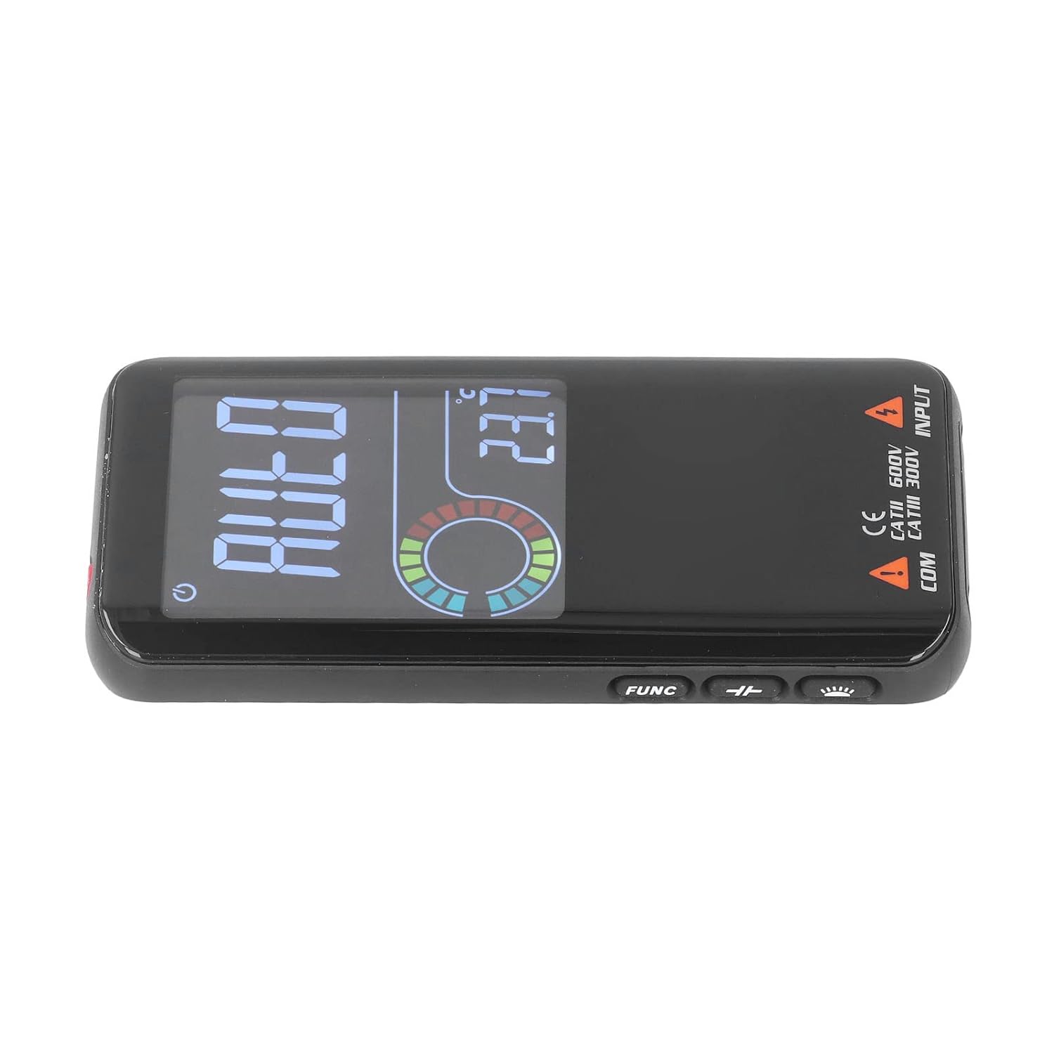
- Ensure the multimeter is powered on. The display will show "AUTO".
- Connect the test leads to the circuit or component you wish to measure.
- The multimeter will automatically detect and display the measurement.

This image shows the multimeter's display indicating "AUTO" mode, signifying its readiness to automatically detect and measure various electrical parameters. The color LCD ensures clear visibility of the mode and readings.
Voltage Measurement (AC/DC)
The multimeter can measure both AC and DC voltage up to 620V.
- Set the multimeter to Auto Mode or select the voltage function (if available via FUNC button).
- Connect the red test lead to the positive (+) side of the circuit and the black test lead to the negative (-) side or ground.
- Read the voltage value on the display.
Capacitance Measurement
Measures capacitance from 1nF to 99.99mF.
- Ensure the capacitor is fully discharged before testing.
- Connect the test leads across the capacitor terminals.
- The capacitance value will be displayed.
Diode Test
Automatically identifies diodes less than 3.0V.
- Connect the red test lead to the anode and the black test lead to the cathode of the diode.
- The forward voltage drop will be displayed. Reverse the leads to check for open circuit.
Duty Cycle Measurement
Measures duty cycle from 0.1% to 99.9% (ACV 2V~620V).
- Connect the test leads across the signal source.
- The duty cycle percentage will be displayed.
Voltage Detection Alarm (NCV)
Detects AC voltage from 90V to 1000V without contact.
- Bring the top of the multimeter close to the AC voltage source.
- The device will emit an alarm sound and/or visual indication when voltage is detected.
Buzzer On/Off (Continuity Test)
Used to check for continuity in a circuit.
- Ensure the circuit is de-energized.
- Connect the test leads across the component or circuit path.
- If continuity exists (low resistance), the buzzer will sound.
Maintenance
Cleaning
- Wipe the case with a damp cloth and mild detergent. Do not use abrasives or solvents.
- Keep the input terminals clean and free from dust or debris.
Battery Replacement
Replace batteries when the low battery indicator appears on the display to ensure accurate readings.
- Refer to the "Battery Installation" section under Setup for detailed steps.
- Always use 2 x 1.5V AAA batteries.
Troubleshooting
| Problem | Possible Cause | Solution |
|---|---|---|
| Multimeter does not power on. | Dead or incorrectly installed batteries. | Check battery polarity or replace batteries. |
| Inaccurate readings. | Low battery, incorrect function selected, or poor test lead connection. | Replace batteries, ensure correct mode (Auto or manual), check test lead connections. |
| "OL" or "-0L" displayed. | Over-range or open circuit. | Check if the measured value exceeds the multimeter's range or if there's a break in the circuit. |
| No continuity buzzer sound. | Open circuit or high resistance. | Ensure the circuit is closed and resistance is low. |
Specifications
| Parameter | Value |
|---|---|
| Display | Color LCD, 9999 Counts |
| Auto Mode | Automatic identification of AC/DC voltage, resistance, continuity |
| Polarity Indication | Automatic indication, '-' for negative polarity |
| Overrange Display | "0L" or "-0L" |
| Sampling Rate | Approx. 3 times per second |
| Automatic Shutdown Time | 5 Minutes |
| Low Battery Indication | LCD display symbol |
| Standby | Screen brightness reduced after approx. 10 seconds without measurement input |
| Working Temperature & Humidity | 0-40℃, 0-80%RH |
| Storage Temperature & Humidity | -10-60℃, 0-70%RH |
| Power Supply | 2 x 1.5V AAA batteries (not included) |
| Working Height | Up to 2000 meters |
| Input Impedance | 10MΩ |
| Maximum Input Voltage | 620V |
| Capacitance Range | 1nF~99.99mF |
| Diode Test | Automatically identifies diodes < 3.0V |
| Duty Cycle | 0.1%~99.9% (ACV 2V~620V) |
| Voltage Detection Alarm (NCV) | 90V~1000V |
Warranty and Support
For warranty information or technical support, please refer to the contact details provided by your retailer or the manufacturer's official website. Keep your purchase receipt as proof of purchase.
Manufacturer: Srliya
Ask a question about this manual
Ask about setup, troubleshooting, compatibility, parts, safety, or missing instructions. Manuals+ will review the question and use this page’s manual context to help answer it.