1. Introduction
This manual provides detailed instructions for the Waveshare 0.71inch Double Eye Round LCD Display Module. This module features two 0.71-inch round IPS LCDs, each with a 160x160 resolution and 65K colors, driven by an embedded GC9D01 controller. It utilizes an SPI interface for communication, making it compatible with various microcontroller boards such as ESP32 and Arduino. This document covers the module's components, specifications, setup, operation, and troubleshooting.
2. Package Content
The package includes the following items:
- 0.71inch DualEye LCD Module x1
- SH1.0 11PIN cable x1
- Convex lens (2pcs) x1

Figure 2.1: Contents of the Waveshare 0.71inch Double Eye Round LCD Display Module package, showing the module, connecting cable, and two convex lenses.
3. Features
Key features of the 0.71inch Double Eye Round LCD Display Module include:
- Double eye LCD module consisting of two 0.71inch round LCD displays.
- IPS panel for wide viewing angles.
- 160x160 resolution with 65K colors for clear and vibrant display effects.
- SPI interface, minimizing required IO pins.
- Compatible with controller boards such as ESP32 and Arduino.
- Embedded GC9D01 driver.

Figure 3.1: Overview of the 0.71inch Double Eye LCD Module highlighting its IPS panel, 160x160 resolution, 65K colors, SPI interface, and GC9D01 driver.
4. Specifications
Detailed specifications for the module are provided below:
| Parameter | Value |
|---|---|
| Operating Voltage | 3.3V / 5V |
| Resolution | 160 × 160 pixels |
| Communication Interface | SPI |
| Display Size | 18 × 18 (mm) |
| Display Panel | IPS |
| Pixel Pitch | 37.5 × 112.5 (µm) |
| Driver | GC9D01 |
| Dimensions | 20.00 × 51.00 (mm) |
| Item Weight | 0.317 ounces |

Figure 4.1: Detailed specifications table for the 0.71inch DualEye LCD Module.
5. Pinout Description
The module communicates via an SPI bus. The following table details the pin connections:
| Pin | Description |
|---|---|
| VCC | Power (3.3V / 5V input) |
| GND | Ground |
| DIN | SPI Data Input |
| CLK | SPI Clock Input |
| CS1 | EYE1 Chip Selection |
| CS2 | EYE2 Chip Selection |
| DC | Data/Command Selection |
| RST1 | EYE1 Reset |
| RST2 | EYE2 Reset |
| BL1 | EYE1 Backlight |
| BL2 | EYE2 Backlight |

Figure 5.1: Pinout diagram for the 0.71inch DualEye LCD Module, showing connections for power, SPI communication, and backlight control.
6. Outline Dimensions
The physical dimensions of the module are as follows:
- Overall Length: 51.00 mm
- Overall Width: 20.00 mm
- Display Diameter: Φ18.00 mm
- Mounting Hole Diameter: ΦM2
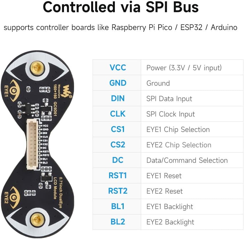
Figure 6.1: Technical drawing illustrating the outline dimensions of the 0.71inch DualEye LCD Module.
7. Setup Instructions
To set up your Waveshare 0.71inch Double Eye Round LCD Display Module, follow these general steps:
- Hardware Connection: Connect the module to your chosen microcontroller board (e.g., ESP32, Arduino) using the provided SH1.0 11PIN cable. Ensure correct pin mapping for VCC, GND, DIN, CLK, CS1, CS2, DC, RST1, RST2, BL1, and BL2 as described in the Pinout section.
- Power Supply: Provide a stable 3.3V or 5V power supply to the VCC pin, depending on your microcontroller's logic level and the module's requirements.
- Software Environment: Install the necessary development environment for your microcontroller (e.g., Arduino IDE, ESP-IDF).
- Library Installation: The module requires specific display drivers. Waveshare provides resources and example code on their official Wiki. It is recommended to visit the Waveshare Wiki for 0.71inch DualEye LCD Module for the latest drivers and example code. Search for the GC9D01 driver and compatible libraries (e.g., modified TFT_eSPI).
- Initial Code Upload: Upload a basic test sketch or example code from the Waveshare Wiki to verify the connection and display functionality. Pay attention to specific board configurations (e.g., ESP32-C3 vs. ESP32-S3) as library compatibility can vary.
Note: Due to the nature of open-source development and frequent updates to microcontroller libraries, specific setup steps and library versions may vary. Always refer to the official Waveshare Wiki for the most current and accurate information.
8. Operating Instructions
Once the module is set up, you can begin programming it to display content:
- SPI Communication: The module uses the Serial Peripheral Interface (SPI) protocol. You will need to initialize the SPI bus on your microcontroller, specifying the clock speed, data order, and mode.
- Chip Select (CS) Management: Since there are two independent displays, each has its own Chip Select (CS1 for EYE1, CS2 for EYE2) and Reset (RST1 for EYE1, RST2 for EYE2) pins. Your code must manage these pins to select which display you are communicating with or resetting.
- Data/Command (DC) Pin: The DC pin differentiates between data and command bytes sent over the SPI bus. Ensure this pin is correctly toggled according to the GC9D01 driver specifications.
- Backlight Control: The BL1 and BL2 pins control the backlights for EYE1 and EYE2, respectively. These can often be controlled via PWM (Pulse Width Modulation) for brightness adjustment.
- Display Initialization: After power-up and reset, the GC9D01 driver requires a specific sequence of commands to initialize the display. This is typically handled by the display library you are using.
- Drawing Graphics: Use the functions provided by your display library to draw pixels, lines, shapes, text, and images onto the display. Remember that the GC9D01 driver internally treats the display as square, so your software needs to account for the round shape and any "missing" pixels if you want to render content accurately within the circular area.
- Frame Buffer Management: Each display has its own video RAM. If you are animating content or displaying complex graphics, consider how you manage the frame buffers for both displays in your microcontroller's memory.
9. Maintenance
To ensure the longevity and optimal performance of your display module:
- Handling: Handle the module with care, avoiding excessive force or bending, especially on the flexible PCB connections.
- Cleaning: If necessary, gently clean the display surface with a soft, lint-free cloth. Avoid abrasive materials or harsh chemical cleaners.
- Storage: Store the module in a dry, anti-static environment, away from direct sunlight and extreme temperatures.
- Power: Always ensure the correct voltage is supplied to prevent damage to the module.
10. Troubleshooting
If you encounter issues with your display module, consider the following troubleshooting steps:
- Display Not Lighting Up:
- Verify power connections (VCC, GND) and ensure the correct voltage (3.3V/5V) is applied.
- Check backlight connections (BL1, BL2) and ensure they are enabled in your code.
- Confirm the display initialization sequence in your code matches the GC9D01 driver requirements.
- No Display Output / Garbled Display:
- Double-check all SPI connections (DIN, CLK, CS1, CS2, DC) for continuity and correct pin mapping.
- Ensure the SPI clock speed is appropriate for the module and your microcontroller.
- Verify that the correct display library and driver (GC9D01) are installed and configured for your specific microcontroller board.
- If using example code, ensure it is compatible with your current library versions and microcontroller model (e.g., ESP32-C3 vs. ESP32-S3). Some users have reported issues with older library versions or specific ESP32 variants.
- Confirm that the Chip Select (CS) and Data/Command (DC) pins are being toggled correctly in your software.
- Only One Eye Working:
- Check the individual CS1/CS2 and RST1/RST2 connections and ensure they are correctly addressed in your code for both displays.
- Verify BL1 and BL2 backlight controls are independently enabled.
- Demo Code Not Compiling or Running:
- Ensure you are using the recommended Arduino IDE or ESP-IDF version.
- Check for library conflicts or outdated library versions. It may be necessary to use specific versions of libraries like TFT_eSPI as recommended by Waveshare's Wiki.
- Confirm board settings in your IDE (e.g., Flash Size, Partition Scheme for ESP32) match the requirements of the demo code.
- Consult the Waveshare Wiki for any updates or specific instructions regarding demo code compatibility.
11. Warranty Information
This product is covered by the standard manufacturer's warranty. For specific details regarding warranty terms, duration, and claims, please refer to the official Waveshare website or contact their customer support directly. Keep your proof of purchase for warranty validation.
12. Support
For further assistance, technical documentation, and the latest resources, please visit the official Waveshare Wiki:
Waveshare 0.71inch DualEye LCD Module Wiki
The Wiki provides detailed tutorials, example code, and community forums that can help with advanced usage and specific project integrations.


