1. Introduction
The Denash CANable 2.0 is an open-source USB to CAN analyzer designed to facilitate communication with CAN bus interfaces. It enumerates as virtual serial ports on your computer, acting as a serial line for CAN bus interaction. This device supports CAN2.0A, CAN2.0B, and CAN FD standards, and is compatible with ARM-based embedded platforms such as Raspberry Pi, Raspberry Pi Zero, and ODROID. Its high-performance ARM Cortex M4 processor ensures efficient and stable operation for various CAN analysis tasks.

Figure 1: Denash CANable 2.0 USB to CAN Analyzer Module. This image shows the compact design of the CANable 2.0 module, highlighting its function as an open-source USB to CAN analyzer that creates virtual serial ports for CAN bus communication.
2. Product Features
- Multi-Standard Support: Compatible with CAN2.0A, CAN2.0B, and CAN FD standards.
- USB Interface: Equipped with a Type-C USB port for modern connectivity.
- Firmware Upgrade: Supports online firmware upgrade and DFU (Device Firmware Upgrade) mode.
- High-Performance Processor: Features an ARM Cortex M4 STM32G431C8T6 processor, operating at up to 170MHz for efficient data processing.
- Platform Compatibility: Designed for compatibility with ARM-based embedded platforms such as Raspberry Pi, Raspberry Pi Zero, and ODROID.
- Local CAN Interface: Functions as a stable and practical local CAN interface when utilizing CandleLight firmware.
- Virtual Serial Ports: Creates virtual serial ports on your computer for seamless CAN bus interface access.
3. Setup Guide
3.1 Package Contents
Verify that your package contains the following items:
- 1 x Denash CANable 2.0 USB to CAN Analyzer Module
- 1 x USB Cable (USB-A to USB-C)
- 1 x Connecting Cable (Jumper Wires)

Figure 2: Package Contents. This image shows the CANable 2.0 module along with the included USB-A to USB-C cable and a set of jumper wires for connections.
3.2 Physical Connection
- Connect the provided USB-A to USB-C cable to the Type-C port on the CANable 2.0 module and to an available USB port on your computer.
- Identify the CAN interface terminal block on the module. Connect your CAN bus wires (CAN High, CAN Low, and Ground) to the corresponding terminals. Refer to Figure 3 for component identification.
- Ensure proper CAN bus termination (typically 120 Ohm) if the CANable 2.0 is at an end of the bus. The module includes a '120R' short circuit cap for this purpose.

Figure 3: Component Identification. This image highlights key components of the CANable 2.0 module, including the CAN interface (green terminal block), BOOT short cap, Terminal resistant short circuit cap (120R), SWD pins, Power indicator light (PWR), Signal light (WORK/STAT), and the Type C USB port.
3.3 Driver and Firmware Installation
The CANable 2.0 typically requires specific firmware to function as a CAN interface. Two common firmware options are CandleLight and slcan.
- CandleLight Firmware: When using CandleLight firmware, the CANable 2.0 enumerates as a local CAN interface on your operating system (e.g., Linux). This provides a stable and practical CAN interface.
- slcan Firmware: With slcan firmware, the device enumerates as a virtual serial port, allowing communication with CAN bus via serial commands.
Refer to the official CANable documentation or community resources for detailed instructions on flashing the desired firmware and installing necessary drivers for your operating system. Firmware updates can be performed online or via DFU mode.
4. Operating Instructions
4.1 Power On and Status Indicators
Once connected via USB, the Power indicator light (PWR) should illuminate, indicating the device is receiving power. The Signal light (WORK/STAT) will indicate CAN bus activity.
4.2 Using with CandleLight Firmware
If your CANable 2.0 is flashed with CandleLight firmware, it will appear as a native CAN interface. On Linux systems, you can typically interact with it using the ip link and candump/cansend utilities from the can-utils package. Ensure the CAN interface is brought up and configured with the correct baud rate.
4.3 Using with slcan Firmware
When using slcan firmware, the device will appear as a serial port (e.g., /dev/ttyUSB0 on Linux, COM port on Windows). You can then use a serial terminal program or a CAN analysis tool that supports the slcan protocol to send and receive CAN messages. The slcan protocol defines commands for setting baud rates, opening/closing the CAN channel, and transmitting/receiving frames.
4.4 CAN Bus Communication
Regardless of the firmware, ensure the CAN bus baud rate configured on the CANable 2.0 matches the baud rate of the CAN network it is connected to. Mismatched baud rates will prevent communication.
5. Maintenance
To ensure the longevity and reliable operation of your Denash CANable 2.0 module, follow these maintenance guidelines:
- Cleaning: Use a dry, soft, lint-free cloth to clean the module. Avoid using liquid cleaners, solvents, or abrasive materials.
- Storage: Store the device in a cool, dry, and dust-free environment when not in use. Keep it away from direct sunlight and extreme temperatures.
- Handling: Handle the module with care to prevent physical damage. Avoid dropping it or subjecting it to excessive force.
- Environmental Protection: Protect the device from moisture, humidity, and corrosive substances.
6. Troubleshooting
If you encounter issues with your CANable 2.0 module, refer to the following troubleshooting steps:
6.1 Device Not Recognized
- Check USB Connection: Ensure the USB cable is securely connected to both the CANable 2.0 and your computer. Try a different USB port or cable.
- Verify Drivers: Confirm that the necessary drivers for the virtual serial port or CAN interface are correctly installed on your operating system.
- Power Indicator: Check if the PWR indicator light is on. If not, the device may not be receiving power.
6.2 No CAN Communication
- CAN Bus Wiring: Double-check the CAN High (CANH), CAN Low (CANL), and Ground (GND) connections to the CAN bus. Ensure they are correctly wired.
- Baud Rate Mismatch: Verify that the baud rate configured for the CANable 2.0 matches the baud rate of the CAN network.
- Termination Resistors: Ensure proper 120 Ohm termination resistors are present at both ends of the CAN bus. The CANable 2.0 has an onboard option for this.
- Firmware Check: Confirm that the correct firmware (CandleLight or slcan) is flashed and properly configured for your application.
6.3 Firmware Update Issues
- DFU Mode: Ensure the device is correctly put into DFU (Device Firmware Upgrade) mode before attempting a firmware flash. Refer to specific firmware documentation for this procedure.
- Software/Tool: Use the recommended flashing tool and firmware file for your specific CANable 2.0 version.
7. Specifications
The following table details the technical specifications of the Denash CANable 2.0 USB to CAN Analyzer Module:

Figure 4: Module Dimensions. This image displays the physical dimensions of the CANable 2.0 module, including its length (45mm / 1.77in), width (16mm / 0.63in), and height (10.5mm / 0.41in) of the terminal block. It also shows the mounting hole pattern with a diameter of 2.2mm / 0.09in.
| Feature | Specification |
|---|---|
| Brand | Denash |
| Model Number | Denashoxtec2m9f4 |
| Microprocessor | For STM32G431C8T6 (ARM Cortex M4) |
| Processor Speed | Up to 170MHz |
| Communicating Chip | For TJA1051T/3 |
| Voltage | DC 3.3V-5V |
| CAN Standards Supported | CAN2.0A, CAN2.0B, CAN FD |
| Firmware Support | CandleLight, slcan |
| Data Transfer Rate (CAN) | 1M, 2M, 5M (Megabits Per Second) |
| ESD Protection | 30kV |
| Hardware Interface | USB Type-C |
| Compatible Devices | Single-Board Computer (e.g., RasPi, ODROID) |
| Compatible OS Family | Linux |
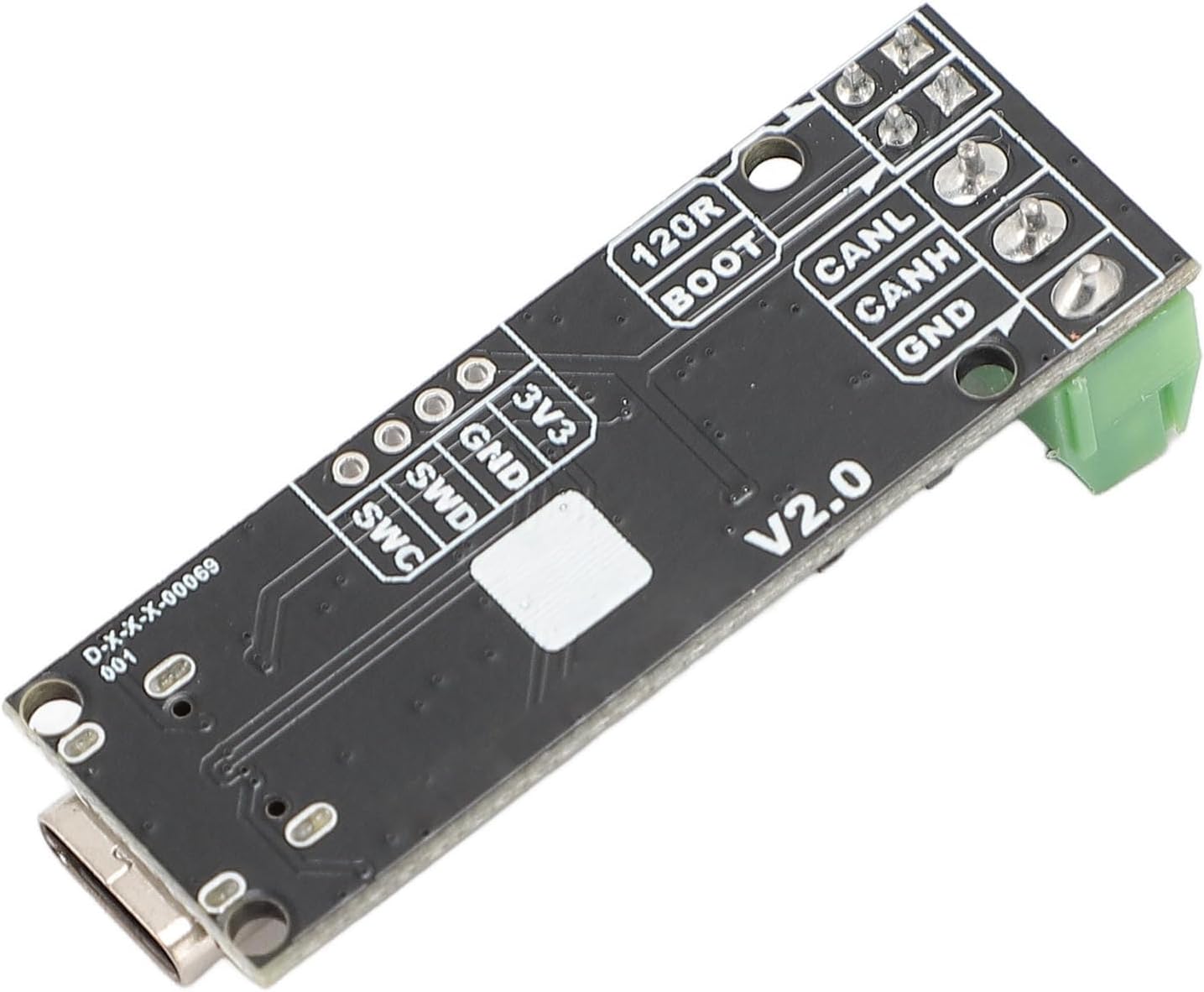
Figure 5: Pinout Diagram (Bottom View). This image details the pinout labels on the underside of the CANable 2.0 module for SWD (SWD, SWC, GND, 3V3) and CAN (CANL, CANH, GND) connections.
8. Warranty Information
This Denash product is covered by a standard manufacturer's warranty. Please refer to the product packaging or the seller's terms and conditions for specific warranty duration and coverage details. The warranty typically covers defects in materials and workmanship under normal use.
9. Support
For technical assistance, troubleshooting, or further inquiries regarding your Denash CANable 2.0 USB to CAN Analyzer Module, please contact the retailer or manufacturer directly. You may find additional resources and community support online for open-source CANable devices.