1. Introduction
This manual provides essential information for the safe and efficient operation of your ZLPOWER 6000W-24V-SPLIT Low Frequency Pure Sine Wave Inverter Charger. Please read this manual thoroughly before installation and use, and retain it for future reference. This inverter charger is designed to convert 24V DC battery power into 120V/240V AC split-phase power, suitable for various applications including RVs, trailers, campers, homes, and boats. It also features a built-in 90A battery charger and a 30A automatic transfer switch.

Figure 1: ZLPOWER 6000W-24V-SPLIT Inverter Charger
2. Safety Information
Always observe the following safety precautions to prevent injury and damage to the equipment:
- Installation must be performed by qualified personnel in accordance with all local and national electrical codes.
- Ensure the inverter is disconnected from all power sources (battery and AC input) before performing any maintenance or wiring.
- Do not expose the inverter to rain, snow, spray, or any liquids.
- Ensure proper ventilation around the inverter to prevent overheating.
- Verify correct polarity when connecting battery cables. Reversing polarity will damage the inverter.
- Use appropriate wire gauges for all connections as specified in the installation guidelines.
- This inverter is ETL certified to UL 1741 standards, ensuring compliance with safety regulations.
3. Product Overview
3.1 Key Features
- 6000W Continuous Pure Sine Wave Output, 18000W Peak Surge Power (20 seconds).
- 24V DC Input, 240V AC Input, 120V/240V AC Split Phase Output.
- Integrated 90A Multi-Stage Battery Charger.
- 30A Automatic Transfer Switch.
- AC Priority / Battery Priority Selector.
- Adjustable Charging Current (0% to 100%).
- DIP Switch Settings for customizable operation (low battery trip, AC input range, output frequency, power saver).
- Automatic Generator Start (AGS) function.
- Pure Copper Low Frequency Transformer for robust performance with inductive loads.
- Multiple Safety Protections: Over/low voltage, overload, short circuit, over-temperature.
- Remote Control Functionality.
3.2 Components and Dimensions
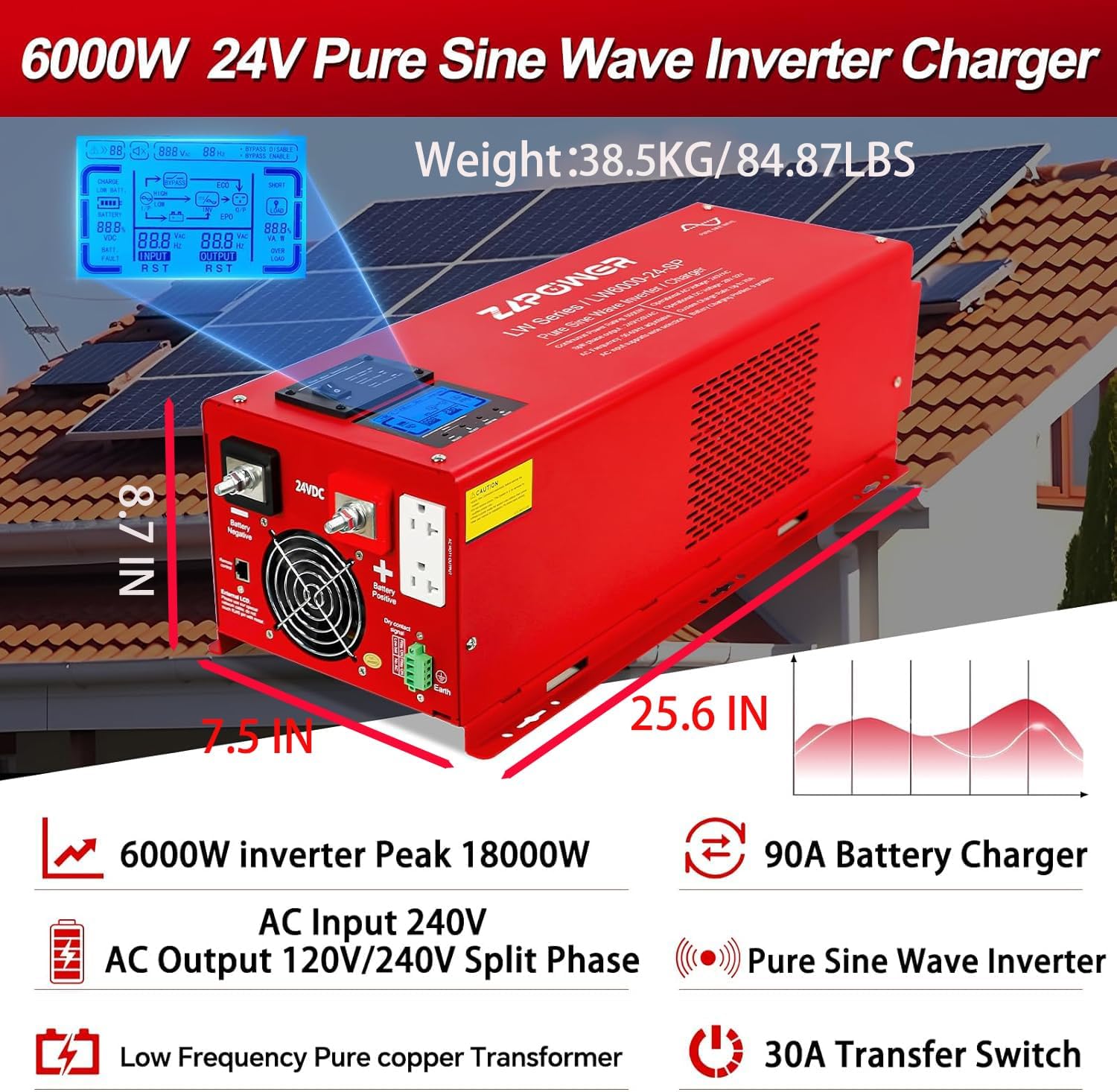
Figure 2: ZLPOWER Inverter Charger with key features and dimensions. The unit weighs 81 pounds and measures approximately 25.6 inches in length, 8.7 inches in width, and 7.5 inches in height.
4. Setup and Installation
Proper installation is crucial for the safe and efficient operation of the inverter charger. Refer to the wiring diagram below for a visual guide.

Figure 3: Connection Diagram illustrating the setup with solar panels, solar controller, battery, utility power/generator, and home appliances.
4.1 Battery Connection
- Ensure the inverter is OFF and all power sources are disconnected.
- This inverter operates with a 24V battery system. Connect two 12V batteries in series to achieve 24V.
- Connect the positive (red) battery cable to the inverter's positive terminal and the negative (black) battery cable to the inverter's negative terminal.
- CAUTION: Be extremely careful not to reverse the polarity, as this will cause severe damage to the inverter.
- Secure all connections tightly.
4.2 AC Input Connection
The AC input allows the inverter to charge batteries from the grid or a generator, and to pass through AC power to loads when available. Use a 3-core AC cable (Live (L), Neutral (N), and Ground (G)).
- Remove the protective cover of the AC input terminal block.
- Connect the Live (L) wire to the terminal labeled 'AC Input L'.
- Connect the Neutral (N) wire to the terminal labeled 'AC Input N'.
- Connect the Ground (G) wire to the grounding screw.
- Ensure all connections are secure and replace the protective cover.
4.3 AC Output Connection
The AC output is where you connect your home appliances or loads. This inverter provides 120V/240V split-phase output. Use appropriate 3-core AC cables for your loads.
- Remove the protective cover of the AC output terminal block.
- Connect the Live (L1) wire for 120VAC output to 'AC Output L1'.
- Connect the Live (L2) wire for 240VAC output to 'AC Output L2'.
- Connect the Neutral (N) wire to 'AC Output N'.
- Connect the Ground (G) wire to the grounding screw.
- Ensure all connections are secure and replace the protective cover.
4.4 Remote Control and Sensor Connections
- Remote Control: Connect the remote control cable to the 'Remote Control' port on the inverter.
- Battery Temperature Sensor: Connect the optional battery temperature sensor to the designated port to optimize charging based on battery temperature.
- Automatic Generator Start (AGS): Connect your generator's start/stop control wires to the AGS terminals. The inverter will automatically start the generator when battery voltage drops below a set threshold.
Video 1: ZLPOWER Hybrid Inverter Installation Guide. This video demonstrates the physical installation steps for the inverter, including battery and AC wiring.
5. Operating Instructions
After successful installation, follow these steps to operate your inverter charger:
5.1 Initial Power-Up
- Ensure all battery and AC connections are secure.
- Turn on the battery breaker (if installed).
- Switch the inverter ON using the main power switch. The LCD display will illuminate.
- If AC input is connected, the inverter will automatically detect it and begin charging the batteries (if needed) and transfer AC power to the loads.
5.2 AC/Battery Priority Settings
The inverter offers flexible priority settings:
- AC Priority (Default): When AC input is available, the inverter charges the battery and transfers AC to power the loads.
- Battery Priority: The inverter will supply power from the battery even when AC input is present. This is ideal for maximizing self-consumption from renewable energy sources.
These settings can be configured via the DIP switches or the optional LCD remote panel.
5.3 DIP Switch Settings
The inverter features five DIP switches for advanced configuration:
- SW1: Low Battery Trip Voltage (adjusts the voltage at which the inverter switches to AC input or shuts down).
- SW2: AC Input Range (sets the acceptable voltage range for AC input).
- SW3: Output Frequency Setting (50Hz or 60Hz).
- SW4: Power Saver Setting (enables or disables power saving mode).
- SW5: Utility/Battery Priority.
Refer to the detailed table in the full manual for specific DIP switch combinations and their corresponding functions.
5.4 LCD Display
The integrated LCD display provides real-time operational status, including input/output voltage, frequency, battery status, and load percentage. It also allows for parameter adjustments.
Video 2: How to Use Your Low Frequency Solar Hybrid Inverter. This video demonstrates the LCD display functions and how to operate the inverter with various loads.
6. Maintenance
Regular maintenance ensures the longevity and optimal performance of your inverter charger:
- Keep the inverter clean and free from dust and debris. Ensure ventilation openings are not obstructed.
- Periodically check all electrical connections for tightness and corrosion.
- Inspect battery cables for any signs of wear or damage.
- Monitor the battery bank's health and ensure proper charging cycles.
7. Troubleshooting
If you encounter issues, refer to the following common problems and solutions:
| Problem | Possible Cause | Solution |
|---|---|---|
| Inverter not turning on | Loose battery connection, low battery voltage, blown fuse. | Check battery connections, charge batteries, replace fuses. |
| No AC output | Overload, inverter fault, AC output breaker tripped. | Reduce load, check fault codes on LCD, reset AC output breaker. |
| Battery not charging | No AC input, AC input breaker tripped, charger fault. | Check AC input connection, reset AC input breaker, consult support. |
| Overload alarm | Connected load exceeds inverter capacity. | Reduce the total load connected to the inverter. |
For persistent issues, contact ZLPOWER customer support.
8. Specifications
| Specification | Value |
|---|---|
| Output Power | 6000 Watts |
| Peak Power | 18000 Watts (for 20 seconds) |
| Input Voltage (DC) | 24 Volts (DC) |
| Input Voltage (AC) | 220-240 Volts (AC) |
| Output Voltage (AC) | 120V/240V Split Phase |
| Frequency | 60 Hz (Adjustable) |
| Battery Charger Current | 90A (Adjustable) |
| Transfer Switch | 30A |
| Certifications | ETL to UL 1741 standards |
| Item Weight | 81 pounds |
| Package Dimensions | 29 x 13 x 12 inches |
9. Warranty and Support
ZLPOWER products are designed for reliability and performance. For warranty information, please refer to the documentation included with your product or visit the official ZLPOWER website.
For technical support, troubleshooting assistance, or to inquire about replacement parts, please contact ZLPOWER customer service. Contact details can typically be found on the product packaging or the manufacturer's website.