1. Introduction
This manual provides essential information for the installation, operation, and maintenance of the PRPYVPEY HGM4020N Generator Smart Controller. The HGM4020N is designed to automatically start and stop the generator set, monitor its operational status, and protect it from abnormal conditions. It features a digital display for various parameters and supports automatic mains failure (AMF) control.

Figure 1: Front view of the HGM4020N Generator Smart Controller.
2. Safety Information
Please read and understand all safety instructions before installing, operating, or performing maintenance on the HGM4020N controller. Failure to follow these instructions may result in personal injury, equipment damage, or death.
- Ensure all power sources are disconnected before installation or maintenance.
- Installation and wiring should only be performed by qualified personnel.
- Protect the controller from moisture, extreme temperatures, and corrosive environments.
- Verify all wiring connections are secure and correct according to the wiring diagram.
- Do not operate the controller with damaged wiring or components.
3. Product Overview
The HGM4020N controller integrates digital, intelligent, and network techniques, used for automatic control and monitoring system of single generator sets. It can carry out functions including automatic start/stop, data measurement, alarm protection, and three remote functions (remote control, remote measurement, and remote communication).
3.1 Terminal Identification
The rear panel of the HGM4020N features various terminals for power input, sensor connections, and control outputs. Refer to the diagram below for a detailed layout of the terminals.
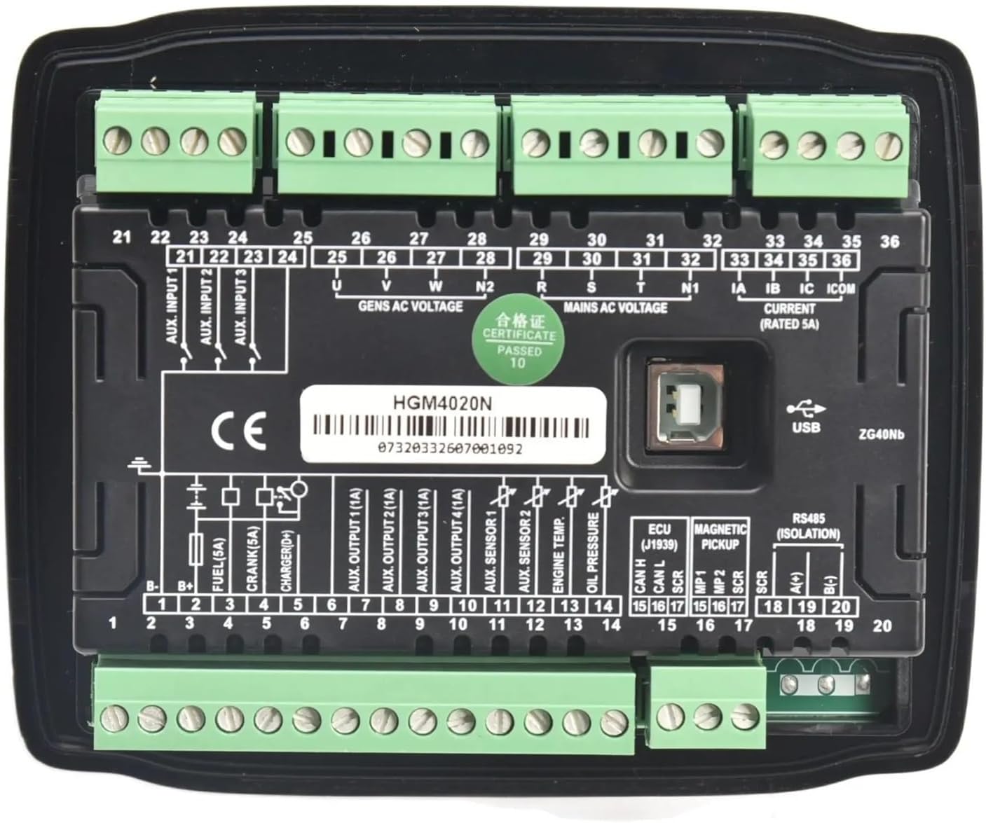
Figure 2: Rear panel of the HGM4020N controller showing terminal connections.
Key terminal groups include:
- Terminals 1-20: DC power input, fuel output, crank output, charger output, auxiliary outputs, sensor inputs (oil pressure, engine temp, fuel level), magnetic pickup, ECU, and RS485 communication.
- Terminals 21-24: Auxiliary inputs.
- Terminals 25-28: Generator AC voltage inputs (U, V, W, N).
- Terminals 29-32: Mains AC voltage inputs (R, S, T, N1).
- Terminals 33-36: Current transformer (CT) inputs (IA, IB, IC, ICOM).


Figure 3: Angled views providing additional perspective on the controller's terminal blocks.
4. Setup and Installation
Careful installation and wiring are crucial for the correct operation of the HGM4020N controller. Refer to the wiring diagram provided with your product for specific connections. The following steps outline a general installation procedure:
- Mounting: Install the controller into a suitable panel cutout, ensuring adequate ventilation and protection from environmental factors. Secure it using the provided mounting clips.
- DC Power Supply: Connect the DC power supply (typically 8-35V DC) to the designated terminals (e.g., B+ and B-). Ensure correct polarity and adequate fusing.
- Generator AC Voltage Input: Connect the generator's three-phase or single-phase AC voltage outputs to terminals 25-28 (U, V, W, N).
- Mains AC Voltage Input (for AMF): If using the Automatic Mains Failure function, connect the utility (mains) AC voltage to terminals 29-32 (R, S, T, N1).
- Current Transformer (CT) Connections: Connect the secondary windings of the current transformers to terminals 33-36 (IA, IB, IC, ICOM) for current measurement. Ensure correct phasing.
- Engine Sensors: Connect engine sensors such as oil pressure, engine temperature, and fuel level to their respective input terminals (e.g., 10, 11, 12, 13).
- Engine Control Outputs: Connect the fuel solenoid, crank motor, and other auxiliary outputs to terminals 3-9 as per your generator's requirements.
- Communication: If remote monitoring is desired, connect the RS485 communication lines to terminals 18-20.
- Final Checks: Double-check all wiring for correctness, security, and insulation before applying power.
5. Operating Instructions
The HGM4020N controller offers both manual and automatic operation modes.
5.1 Manual Operation
- Start: Press the Manual button, then the Start button. The controller will initiate the cranking sequence.
- Stop: Press the Stop button. The generator will shut down.
5.2 Automatic Operation (AMF Mode)
In AMF mode, the controller monitors the mains power supply. If the mains power fails or falls outside acceptable limits, the controller will automatically start the generator. When mains power is restored, the controller will transfer the load back to the mains and shut down the generator after a cooling period.
- Press the Auto button to enable automatic mode.
- The controller will continuously monitor the mains supply.
- Upon mains failure, the generator will start automatically.
- Upon mains restoration, the generator will stop automatically after a cool-down period.
5.3 Parameter Viewing
Use the navigation buttons on the front panel to scroll through various generator parameters displayed on the LCD screen, such as voltage, current, frequency, engine speed, oil pressure, and engine temperature.
6. Maintenance
Regular maintenance ensures the longevity and reliable operation of your HGM4020N controller.
- Cleaning: Keep the controller's surface clean and free from dust. Use a soft, dry cloth. Do not use abrasive cleaners or solvents.
- Connections: Periodically check all wiring connections for tightness and signs of corrosion. Loose connections can lead to intermittent operation or damage.
- Environment: Ensure the operating environment remains within the specified temperature and humidity ranges.
- Firmware: Consult the manufacturer or authorized service center for information on firmware updates.
7. Troubleshooting
This section provides solutions to common issues encountered with the HGM4020N controller. For complex problems, contact technical support.
| Problem | Possible Cause | Solution |
|---|---|---|
| Controller does not power on | No DC power supply; Blown fuse; Loose wiring. | Check DC power input; Replace fuse; Verify wiring connections. |
| Generator fails to start | Low fuel; Low battery; Engine fault; Incorrect wiring. | Check fuel level; Check battery voltage; Inspect engine for faults; Verify start/fuel wiring. |
| Incorrect readings on display | Sensor fault; Incorrect sensor wiring; Incorrect parameter settings. | Check sensor connections and functionality; Verify wiring; Review controller settings. |
| Generator shuts down unexpectedly | Overload; Low oil pressure; High engine temperature; Other alarm condition. | Check for alarm messages on display; Address the specific alarm condition. |
8. Specifications
The following are the general specifications for the PRPYVPEY HGM4020N Generator Smart Controller:
- Model: HGM4020N
- DC Supply: 8-35V DC continuous
- AC Voltage Input: 15-360V AC (Ph-N), 26-620V AC (Ph-Ph)
- Frequency: 50/60Hz
- Current Input: 5A rated (via CTs)
- Operating Temperature: -25°C to +70°C
- Dimensions: Approximately 1.18 x 0.79 x 0.39 inches (Package Dimensions)
- Weight: Approximately 1.76 ounces
- Communication: RS485
9. Warranty and Support
For warranty information, please refer to the terms and conditions provided by your seller or contact PRPYVPEY directly. Keep your purchase receipt as proof of purchase.
For technical support or inquiries not covered in this manual, please contact your product supplier or an authorized service center. When contacting support, please have your product model (HGM4020N) and purchase details readily available.