1. Introduction
This manual provides essential instructions for the proper installation, operation, and maintenance of your Naroote LLW-50 Digital Fuel Flowmeter. This electronic digital flowmeter is designed for precise measurement of various liquids, including fuel, water, and gas. Its compact size, high accuracy, and modular design make it suitable for a wide range of applications in industrial, commercial, and transportation sectors.
Key features include:
- High Accuracy: Ensures reliable and precise measurement results.
- Modular Design: Allows integration with output modules, sensors, and remote transmitters for enhanced versatility.
- Easy Maintenance: Internal components are designed for straightforward replacement and upkeep.
- Wide Application: Suitable for use in petroleum, medicine, transportation, and commerce.
- Broad Measurement Range: Operates within a range of 35-200 L/Min, supporting multiple units (L, GAL, PTS, QTS).
2. Safety Information
Please read and understand all safety instructions before installing or operating the flowmeter. Failure to follow these instructions may result in equipment damage, personal injury, or inaccurate readings.
- Ensure the flowmeter is installed by qualified personnel in accordance with local codes and regulations.
- Verify that the working pressure of the system does not exceed the maximum working pressure of the flowmeter (10 BAR).
- Always handle batteries with care. Do not mix old and new batteries, or different types of batteries.
- Do not attempt to disassemble or repair the device beyond the scope described in this manual. Contact support for assistance.
- Ensure proper sealing and connections to prevent leaks when handling flammable or hazardous liquids.
- Always wear appropriate personal protective equipment (PPE) when working with liquids or gases.
3. Product Overview
The Naroote LLW-50 Digital Fuel Flowmeter features a robust aluminum alloy body and a clear digital display for easy reading of measurements. The device is designed for inline installation with a 2-inch inlet and outlet size.

Figure 3.1: Front view of the Naroote LLW-50 Digital Fuel Flowmeter. This image shows the overall design of the flowmeter, including the main body and the digital display unit.
3.1 Components and Display
The flowmeter consists of a main body with threaded inlet/outlet ports and a digital display module. The display module includes a liquid crystal display (LCD) and two control buttons.

Figure 3.2: Close-up view of the digital display and control buttons. The display shows current flow and total cumulative volume. The buttons are labeled 'DISPLAY' and 'CALIBRATE'.
- Digital Display: Shows real-time flow rate, single count, and total cumulative count.
- DISPLAY Button: Used to cycle through different display modes (e.g., single count, total count, unit selection).
- CALIBRATE Button: Used for calibration adjustments.
- RESET/TOTAL (on display): Indicates the function to reset the single count or view the total cumulative count.
- Flow Direction Arrow: An arrow is typically molded onto the meter body, indicating the correct direction of fluid flow. Ensure fluid flows in this direction for accurate readings.
4. Setup
4.1 Battery Installation
The Naroote LLW-50 flowmeter requires two (2) AAA LR03 batteries (not included) for operation. The battery compartment is typically located on the underside of the display module. The model number is also indicated under the battery cover.
- Carefully remove the battery compartment cover.
- Insert two AAA LR03 batteries, ensuring correct polarity (+/-).
- Replace the battery compartment cover securely.
4.2 Physical Installation
The flowmeter is designed for inline installation within a piping system. It has a 2-inch inlet and outlet size.
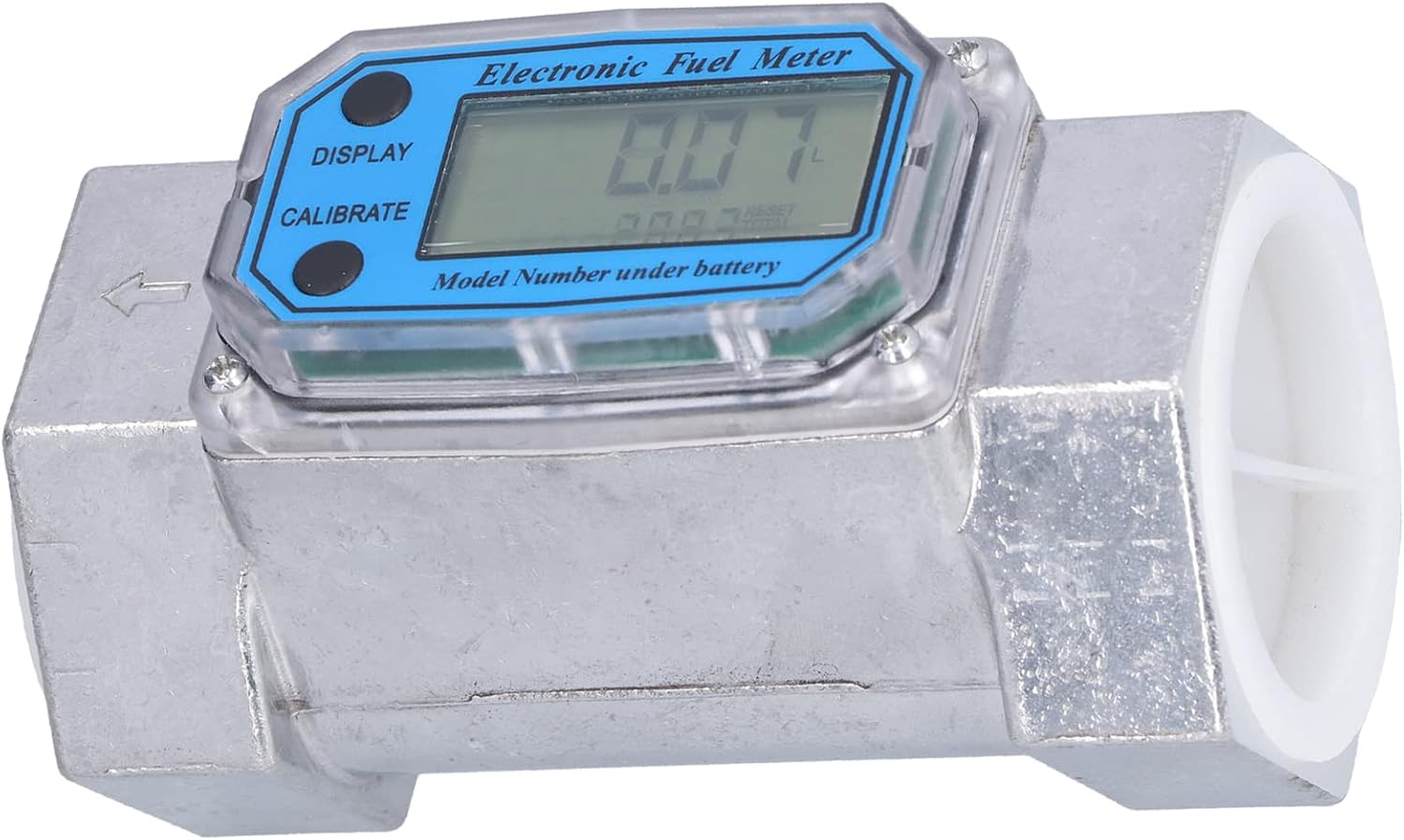
Figure 4.1: Angled view of the flowmeter, highlighting the 2-inch inlet and outlet ports and the flow direction arrow.
- Ensure the system is depressurized and drained before installation.
- Identify the correct flow direction indicated by the arrow on the flowmeter body.
- Install the flowmeter into the pipeline, ensuring that the fluid flows in the direction of the arrow.
- Use appropriate sealing materials (e.g., PTFE tape) on threaded connections to prevent leaks.
- Tighten connections securely, but do not overtighten to avoid damage.
- After installation, slowly repressurize the system and check for any leaks.
5. Operating Instructions
5.1 Power On/Off
The flowmeter typically powers on automatically when fluid flow is detected or when a button is pressed. It will enter a low-power sleep mode after a period of inactivity to conserve battery life.
5.2 Display Modes and Unit Selection
Press the DISPLAY button to cycle through different measurement displays:
- Single Count: Shows the current batch measurement (0.00-9999.9).
- Total Cumulative Number: Shows the grand total of all measured fluid (0-999999).
- Unit Selection: Allows selection of measurement units (Liters, Gallons, Pints, Quarts). To change units, press and hold the DISPLAY button until the unit starts flashing, then press DISPLAY repeatedly to cycle through options. Press CALIBRATE or wait for a few seconds to confirm the selection.
5.3 Resetting Measurements
To reset the Single Count (batch measurement), locate the 'RESET/TOTAL' indication on the display. While viewing the single count, press and hold the CALIBRATE button until the single count resets to zero. The total cumulative number cannot be reset by the user through normal operation.
5.4 Calibration
The flowmeter is factory calibrated to an accuracy of ±1%. If recalibration is required due to specific application needs or significant discrepancies, use the CALIBRATE button. The exact calibration procedure may vary; refer to the detailed instructions provided with the device or contact technical support for advanced calibration steps. Generally, calibration involves flowing a known volume of liquid and adjusting the meter's reading to match the known volume.
6. Maintenance
The Naroote LLW-50 flowmeter is designed for easy maintenance. Regular inspection and cleaning will ensure optimal performance and longevity.
- Cleaning: Periodically clean the exterior of the flowmeter with a soft, damp cloth. Do not use abrasive cleaners or solvents that could damage the display or housing.
- Internal Components: The internal components are designed to be easily replaceable. If a component requires replacement, ensure the system is depressurized and drained before opening the meter. Use only genuine Naroote replacement parts.
- Battery Replacement: Replace batteries when the low battery indicator appears on the display or when the display becomes dim. Refer to Section 4.1 for battery installation instructions.
- Storage: If storing the flowmeter for an extended period, remove the batteries to prevent leakage and store the device in a dry, temperate environment.
7. Troubleshooting
This section addresses common issues you might encounter with your flowmeter.
| Problem | Possible Cause | Solution |
|---|---|---|
| No display or dim display | Dead or low batteries; Incorrect battery installation | Replace batteries with new AAA LR03 batteries, ensuring correct polarity. |
| Inaccurate readings | Incorrect calibration; Air in the line; Flow direction incorrect; Sensor obstruction | Check calibration (Section 5.4); Bleed air from the system; Verify flow direction matches arrow on meter; Inspect for internal obstructions. |
| No flow detected | No fluid flow; Flow below minimum range; Sensor malfunction | Ensure fluid is flowing; Verify flow rate is within 35-200 L/Min range; Contact support if sensor is suspected. |
| Leaks at connections | Improper sealing; Loose connections | Depressurize system, re-apply sealing tape/compound, and re-tighten connections. |
If you encounter issues not listed here or if the suggested solutions do not resolve the problem, please contact Naroote customer support.
8. Specifications
Technical specifications for the Naroote LLW-50 Digital Fuel Flowmeter:
| Specification | Value |
|---|---|
| Item Type | Meter |
| Material | Aluminum alloy |
| Model | LLW-50 |
| Inlet and Outlet Size | 2 inches |
| Calculation Accuracy | ±1% |
| Working Voltage | 2.3V-3.3V |
| Maximum Working Pressure | 10 BAR |
| Range | 35-200 L/Min |
| Single Count Range | 0.00-9999.9 |
| Total Cumulative Number Range | 0-999999 |
| Unit of Measurement Support | L, GAL, PTS, QTS |
| Battery Specification | 2 x AAA LR03 batteries (not included) |
| Item Weight | 1.52 pounds |
| Package Dimensions | 5.91 x 3.54 x 3.54 inches |
| Manufacturer | Naroote |
9. Warranty and Support
For warranty information, technical support, or service inquiries, please contact your retailer or the manufacturer, Naroote, directly. Please have your product model number (LLW-50) and purchase details available when contacting support.
Manufacturer: Naroote