1. Introduction
The Srliya CM83B is a compact and lightweight digital clamp meter designed for electrical power numerical testing. It offers a variety of functions including AC current, AC/DC voltage, resistance, capacitance, and specialized features like NCV, RCD, and VFD measurements. This manual provides essential information for the safe and effective operation, maintenance, and troubleshooting of your device.
Please read this manual thoroughly before using the CM83B clamp meter to ensure proper functionality and to prevent potential hazards.
2. Safety Information
WARNING: To avoid electric shock or personal injury, please read and understand all safety information before using this product. Always adhere to local and national safety codes.
- This device is rated CAT III 600V. Do not exceed the maximum input values specified for each function.
- Do not use the meter if it appears damaged or if the test leads are damaged.
- Ensure the battery cover is securely closed before operation.
- Do not apply voltage to the input terminals when the function switch is set to current, resistance, capacitance, or diode/continuity.
- Use caution when working with voltages above 30V AC RMS, 42V peak, or 60V DC. These voltages pose a shock hazard.
- Always disconnect the test leads from the circuit before changing functions.
- Do not operate the meter in explosive gas, vapor, or dusty environments.
3. Product Overview
Familiarize yourself with the components of your Srliya CM83B Digital Clamp Meter:
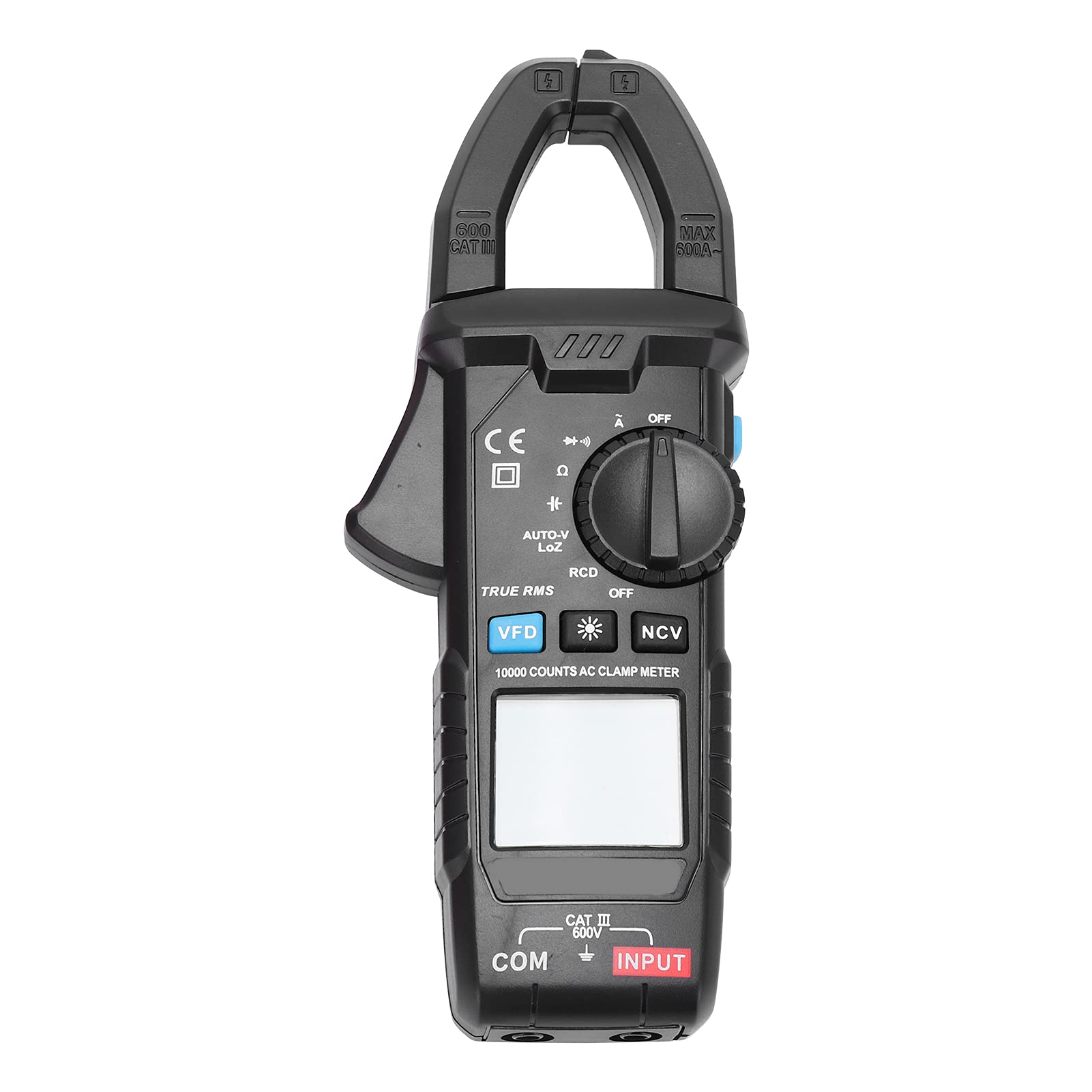
Figure 3.1: Angled view of the CM83B Digital Clamp Meter, showing the display, function dial, and clamp jaw.

Figure 3.2: Front view of the CM83B Digital Clamp Meter, highlighting the display, function dial, and input terminals.
Key Components:
- Clamp Jaw: Used for non-contact AC current measurement. Features a 30mm opening width.
- NCV Sensor: Non-Contact Voltage detection area.
- LCD Display: High-definition digital display with 10,000 counts, backlight, and data retention.
- Function Dial: Rotary switch to select measurement modes (AC Current, AC/DC Voltage, Resistance, Capacitance, Diode/Continuity, NCV, RCD, VFD, AUTO-VLOZ, OFF).
- Buttons:
- VFD: Activates Variable Frequency Drive AC Frequency Measurement.
- *: Backlight button.
- NCV: Activates Non-Contact Voltage detection.
- RCD: Activates Leakage Switch Protector Test.
- AUTO-VLOZ: Activates Low Impedance Voltage Measurement.
- TRUE RMS: Indicates True Effective Value measurement capability.
- Input Terminals (COM, INPUT): For connecting test leads for voltage, resistance, capacitance, and diode/continuity measurements.
4. Setup
4.1 Battery Installation
- Ensure the meter is turned OFF.
- Locate the battery compartment on the back of the meter.
- Using a screwdriver, open the battery back cover.
- Insert two (2) 1.5V AAA batteries, observing the correct polarity (+/-).
- Replace the battery back cover and secure it with the screw.
4.2 Connecting Test Leads

Figure 4.1: The CM83B Clamp Meter shown with its red and black test leads connected to the input terminals.
- For voltage, resistance, capacitance, and diode/continuity measurements, insert the black test lead into the 'COM' (common) terminal.
- Insert the red test lead into the 'INPUT' terminal.
- Ensure the test leads are fully inserted and securely connected.
5. Operating Instructions
The CM83B features an auto-ranging function, simplifying operation by automatically selecting the appropriate measurement range.
5.1 Power On/Off
- To power on, rotate the function dial from 'OFF' to any desired measurement function.
- To power off, rotate the function dial to the 'OFF' position. The meter also features automatic shut-down to conserve battery life.
5.2 AC Current Measurement (Clamp Function)

Figure 5.1: Close-up view of the clamp jaw, used for non-contact AC current measurements.
- Rotate the function dial to the 'A' (AC Current) position.
- Press the clamp trigger to open the jaw.
- Enclose a single conductor (not a cable with multiple conductors) within the clamp jaw.
- Release the trigger to close the jaw securely around the conductor.
- Read the AC current value on the LCD display.
5.3 AC/DC Voltage Measurement
- Connect the test leads as described in Section 4.2.
- Rotate the function dial to the 'V' (Voltage) position. The meter will automatically detect AC or DC voltage.
- Touch the red test probe to the positive side of the circuit and the black test probe to the negative side or ground.
- Read the voltage value on the LCD display.
5.4 Resistance Measurement (Ω)
- Connect the test leads.
- Rotate the function dial to the 'Ω' (Resistance) position.
- Ensure the circuit or component under test is de-energized.
- Touch the test probes across the component or circuit to be measured.
- Read the resistance value on the LCD display.
5.5 Capacitance Measurement (F)
- Connect the test leads.
- Rotate the function dial to the 'F' (Capacitance) position.
- Ensure the capacitor is fully discharged before testing to prevent damage to the meter.
- Touch the test probes across the capacitor terminals.
- Read the capacitance value on the LCD display.
5.6 Diode Test / Continuity Check
- Connect the test leads.
- Rotate the function dial to the 'Ω' (Resistance) position. The meter features auto recognition for buzzer/diode.
- For Diode Test: Touch the red probe to the anode and the black probe to the cathode of the diode. The display will show the forward voltage drop. Reverse the probes; the display should show 'OL' (Open Line).
- For Continuity Check: Touch the test probes across the circuit or component. If continuity exists (low resistance), the buzzer will sound.
5.7 NCV (Non-Contact Voltage) Detection
- Rotate the function dial to the 'NCV' position.
- Move the NCV sensor (located at the top of the meter) close to the conductor or outlet you wish to test.
- The meter will emit an audible beep and the LED indicator will flash when AC voltage is detected.
5.8 RCD (Leakage Switch Protector Test)
- Rotate the function dial to the 'RCD' position.
- Follow specific instructions for RCD testing as per local electrical safety standards and the RCD device being tested. This function is for testing leakage switch protectors.
5.9 VFD (Variable Frequency Drive AC Frequency Measurement)
- Rotate the function dial to the 'VFD' position.
- This mode is used for measuring AC frequency in variable frequency drive systems. Connect test leads as for voltage measurement.
5.10 AUTO-VLOZ (Low Impedance Voltage Measurement)
- Rotate the function dial to the 'AUTO-VLOZ' position.
- This function provides low impedance voltage measurement, which can help detect ghost voltages by placing a load on the circuit.
5.11 True Effective Value (True RMS)
The CM83B features True RMS measurement, which provides accurate readings for non-sinusoidal waveforms, common in modern electrical systems.
5.12 Data Hold and Backlight
- Data Hold: Press the 'HOLD' button (often integrated with another function or indicated by a symbol like 'H') to freeze the current reading on the display. Press again to release.
- Backlight: Press the '*' button to turn on the LCD backlight for improved visibility in low-light conditions. Press again to turn off.
6. Maintenance
6.1 Cleaning
- Wipe the meter with a damp cloth and mild detergent. Do not use abrasives or solvents.
- Ensure the meter is completely dry before use.
6.2 Battery Replacement
When the battery indicator appears on the display, replace the batteries as described in Section 4.1. Always use two new 1.5V AAA batteries.
Remove batteries if the meter is not used for an extended period to prevent leakage.
7. Troubleshooting
| Problem | Possible Cause | Solution |
|---|---|---|
| Meter does not power on. | Dead or incorrectly installed batteries. | Replace batteries, ensuring correct polarity. |
| No reading or 'OL' displayed. | Open circuit, incorrect function selected, or out of range. | Check connections, select appropriate function, or verify measurement is within range. |
| Inaccurate readings. | Poor test lead contact, external interference, or low battery. | Ensure good contact, move away from strong electromagnetic fields, or replace batteries. |
| Buzzer not working for continuity. | High resistance in circuit. | The buzzer only sounds for very low resistance. Check resistance value on display. |
8. Specifications
| Feature | Specification |
|---|---|
| Model | CM83B |
| Material | ABS |
| Power Supply | 2 x 1.5V AAA Batteries (Not Included) |
| Jaw Opening Width | Approx. 30mm / 1.2in |
| AC Current (A) | 0~1A/10A/100A/600A |
| AC Voltage (V) | 0~100V/600V |
| DC Voltage (V) | 0~100V/600V |
| Resistance (Ω) | 0~1KΩ/10KΩ/100KΩ/10MΩ |
| Capacitance (F) | 0~600μF/6000μF |
| Display Count (Maximum) | 10000 Counts |
| Range Selection | Auto Range |
| Buzzer/Diode | Auto Recognition |
| NCV (Non-Contact Voltage) | Support |
| Clamp Head Lighting | Support |
| Screen Light | LCD Backlight |
| Automatic Shut-Down | Support |
| Data Retention | Support |
| True Effective Value | Support |
| RCD Measurement | Leakage Switch Protector Test |
| AUTO-VLOZ | Low Impedance Voltage Measurement |
| VFD | AC Frequency Variable Current Measurement |
| AC Frequency Measurement | Support |
| Working Environment | 0~40℃ |
| Storage Temperature | -10~50℃ |
| Security Level | IEC611010-1, CAT III 600V |
| Item Model Number (Manufacturer) | Srliyagr67wzfovk |
| Parcel Dimensions | 22 x 11 x 5 cm; 400 g |
| Country of Origin | China |
9. Warranty and Support
For warranty information or technical support, please contact the manufacturer or your point of purchase. Keep your purchase receipt as proof of purchase.
Manufacturer: Srliya