1. Introduction
This manual provides essential information for the safe and efficient installation, operation, and maintenance of your Garosa NLQ4 125 4P Automatic Transfer Switch (ATS). This device is designed to automatically switch between a normal power supply and a backup power supply, ensuring continuous power for critical loads. Please read this manual thoroughly before installation and use.
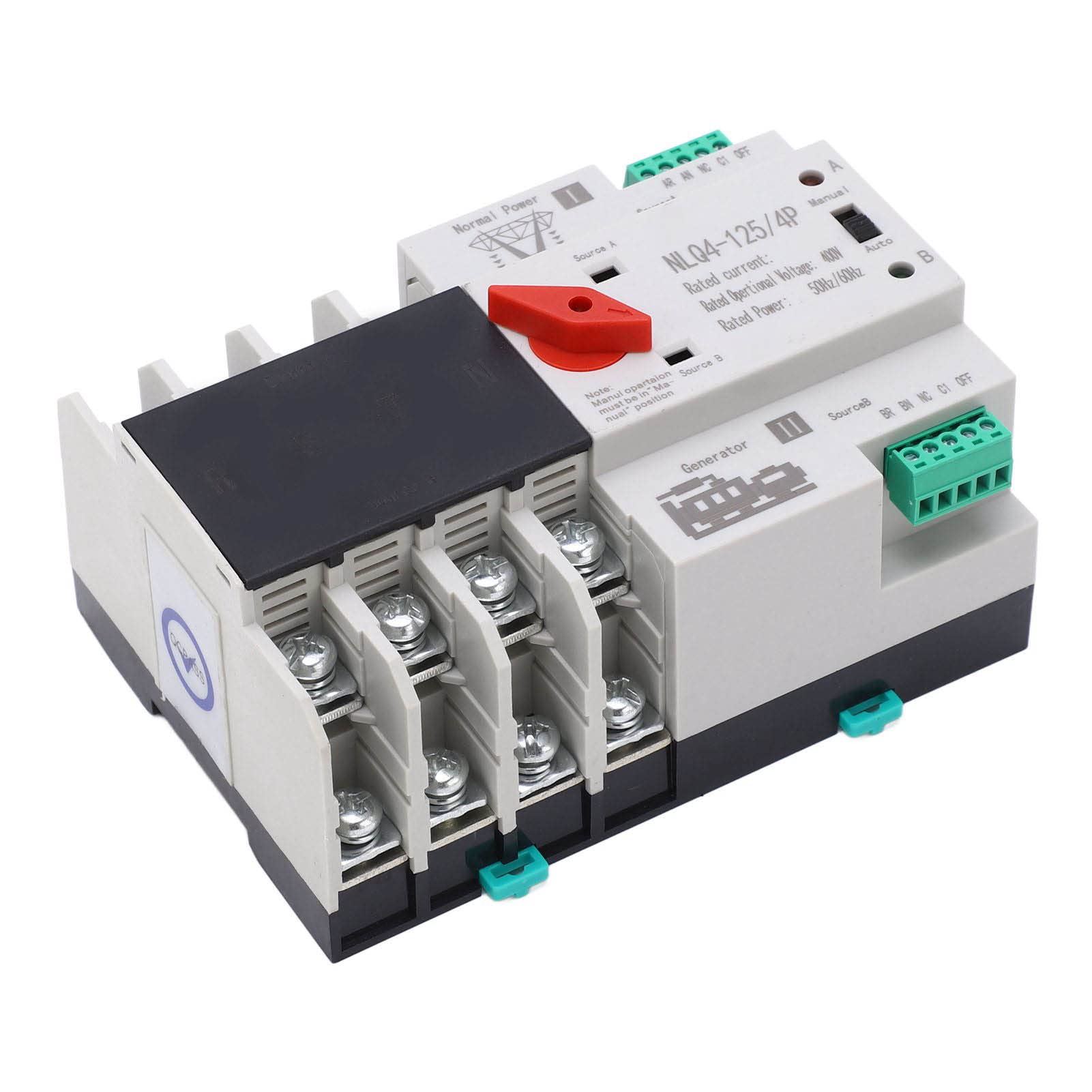
Figure 1: Front view of the Garosa NLQ4 125 4P Automatic Transfer Switch.
2. Safety Information
WARNING: Electrical shock hazard. Installation and servicing must be performed by qualified personnel only. Disconnect all power sources before working on the switch.
- Always ensure the main power supply is disconnected before attempting any installation, wiring, or maintenance.
- Wear appropriate personal protective equipment (PPE) including insulated gloves and safety glasses.
- Verify all wiring connections are secure and correct according to local electrical codes and wiring diagrams.
- Do not operate the switch if it appears damaged or has been exposed to moisture.
- The maximum surrounding temperature should not exceed 40°C, and the minimum should not be lower than -5°C. The average temperature in 24 hours should not be higher than 35°C.
- The altitude of the installation site should not be higher than 2000m.
- When the maximum temperature is 40°C, the relative humidity of the installation site should not exceed 50%. At lower temperatures, higher humidity is permissible (e.g., 90% at 25°C). Take measures to prevent condensation.
3. Product Overview
The Garosa NLQ4 125 4P Automatic Transfer Switch is a robust device designed for seamless power transition. It features excellent insulation, easy installation, and a long service life. The switch ensures continuity, reliability, and safety of power supply by automatically switching to a backup source when the normal power supply is interrupted.
Key Features:
- Automatic and Manual Operation: Allows for flexible control over power transfer.
- Millisecond Switching: Ensures minimal interruption during power transitions.
- Durable Construction: Made from flame-retardant PC material with excellent conductivity, anti-aging properties, and safety.
- High Insulation: Provides enhanced safety and reliability.
- Wide Application: Suitable for homes, shopping malls, factories, laboratories, farms, and other environments requiring continuous power.

Figure 2: Angled view of the ATS, highlighting the terminal connections.
4. Specifications
| Parameter | Value |
|---|---|
| Model | NLQ4 125 4P |
| Rated Current | 20A (This model) |
| Rated Frequency | 50Hz / 60Hz |
| Insulation Voltage | AC690V 50Hz |
| Rated Voltage | AC400V 50Hz |
| Grade | PC grade |
| Specification | 4P |
| Electrical Life | 2000 times |
| Mechanical Life | 5000 times |
| Rated Short Circuit Current | 50kA |
| Rated Impulse Withstand Voltage | 8kV |
| Control Circuit Rated Voltage | AC220V (85% Us - 110% Us) |
| Auxiliary Circuit | Two relays, each with two sets of capacity: AC220V 50Hz ≤ 5y |
| Item Weight | Approximately 1.75 pounds |
| Package Dimensions | Approximately 5.91 x 4.33 x 3.54 inches |

Figure 3: Top view of the ATS, showing model and rating labels.
5. Setup and Installation
Installation of the Automatic Transfer Switch should only be performed by a qualified electrician in accordance with all national and local electrical codes. Incorrect installation can lead to serious injury or damage to equipment.
Installation Steps:
- Power Disconnection: Before beginning any work, ensure that both the normal power supply (Source A) and the backup power supply (Source B/Generator) are completely disconnected and locked out. Verify with a voltage tester.
- Mounting: Mount the ATS securely in a suitable electrical enclosure or panel, ensuring adequate ventilation and clearance for wiring.
- Wiring Main Power (Source A): Connect the normal power supply (utility) to the designated "Normal Power" or "Source A" terminals on the ATS. Ensure correct phase and neutral connections for a 4P system.
- Wiring Backup Power (Source B): Connect the backup power supply (generator) to the designated "Generator" or "Source B" terminals on the ATS. Ensure correct phase and neutral connections.
- Wiring Load: Connect the load circuits (circuits to be powered by the ATS) to the output terminals of the ATS.
- Control Circuit Wiring: Connect the control circuit as per the wiring diagram provided with the product. This typically involves connections for automatic operation and status indication. The rated control voltage is AC220V.
- Grounding: Ensure the ATS and its enclosure are properly grounded according to electrical codes.
- Verification: Double-check all wiring connections for tightness and correctness. Ensure no loose strands or exposed wires.
- Initial Power-Up: Once all connections are verified, restore power to the backup source first, then the normal power source. Observe the ATS operation.
Note: Refer to the detailed wiring diagram included with your product packaging for specific connection points and configurations.
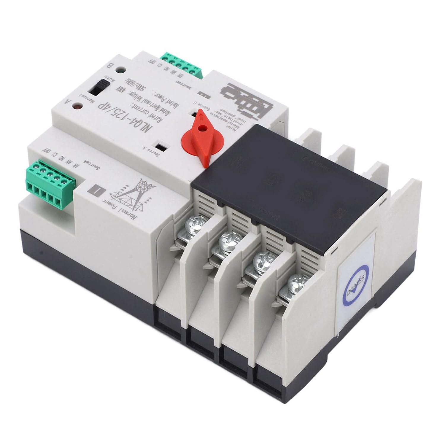
Figure 4: Angled view showing the wiring terminals for power sources and load.
6. Operating Instructions
The NLQ4 125 4P ATS can operate in both automatic and manual modes.
Automatic Mode:
- Set the selector switch (red handle) to the "Auto" position (typically labeled 'B' or 'II' for backup, or 'A' for normal, depending on the specific model's labeling convention for auto mode).
- In this mode, the ATS will continuously monitor the normal power supply (Source A).
- If the normal power supply fails or drops below acceptable levels, the ATS will automatically switch the load to the backup power supply (Source B/Generator) after a short delay.
- When the normal power supply is restored, the ATS will automatically switch the load back to the normal power supply after a short delay.
- The switching process is designed to be completed in milliseconds to minimize power interruption.
Manual Mode:
- To manually switch between power sources, set the selector switch (red handle) to the "Manual" position.
- Then, manually move the handle to position 'I' for Normal Power (Source A) or position 'II' for Backup Power (Source B/Generator).
- Important Note: Manual operation must be in the "Manual" position. Do not force the switch if it is in "Auto" mode.

Figure 5: View of the ATS showing the red selector handle for Manual/Auto operation.
7. Maintenance
Regular maintenance ensures the longevity and reliable operation of your ATS. Always disconnect all power sources before performing any maintenance.
- Visual Inspection (Quarterly):
- Check for any signs of physical damage, discoloration, or overheating.
- Inspect wiring for loose connections, frayed insulation, or corrosion.
- Ensure the operating handle moves freely and is not obstructed.
- Cleaning (Annually):
- With power disconnected, use a dry, lint-free cloth or a soft brush to remove any dust or debris from the exterior and interior (if accessible).
- Do not use liquid cleaners or solvents.
- Functional Test (Annually):
- Simulate a power outage from the normal source to verify the ATS switches to the backup source.
- Restore normal power to ensure the ATS switches back correctly.
- Test manual operation by switching the handle between positions.
- Environmental Conditions: Ensure the installation environment continues to meet the specified temperature and humidity requirements to prevent condensation and operational issues.

Figure 6: Close-up view of the power terminals, important for inspection during maintenance.
8. Troubleshooting
If you encounter issues with your ATS, refer to the following troubleshooting guide. For problems not listed or if issues persist, contact qualified service personnel.
| Problem | Possible Cause | Solution |
|---|---|---|
| ATS does not switch to backup power during outage. |
|
|
| ATS does not switch back to normal power when restored. |
|
|
| No power to load from either source. |
|
|
9. Warranty and Support
This Garosa product is manufactured to high-quality standards. For warranty information, please refer to the specific warranty terms provided at the time of purchase or contact your retailer. Keep your purchase receipt as proof of purchase.
For technical support or service inquiries, please contact Garosa customer service or your authorized dealer. When contacting support, please have your product model number (NLQ4 125 4P) and purchase details available.
Manufacturer: Garosa

Figure 7: Garosa brand logo.