1. Introduction
This manual provides essential information for the proper installation, function, and maintenance of the LBAXSXP CE-KFR26G/Y-11D.D.01.NP2-1 Indoor Unit Control Board. This circuit board is designed as a replacement part for compatible Midea air conditioning indoor units, specifically for 'Cool' models. It is crucial to read and understand these instructions before attempting any installation or service.
2. Safety Information
WARNING: Electrical shock hazard. Disconnect power before servicing. Installation and service should only be performed by qualified and experienced technicians. Failure to follow these instructions could result in serious injury, death, or property damage.
- Always disconnect the main power supply to the air conditioning unit before beginning any work on the control board.
- Ensure proper grounding of the unit.
- Do not touch live electrical components.
- Verify that the replacement board matches the original board's specifications and model number.
- Handle the PCB by its edges to avoid damaging components or introducing static discharge.
3. Product Overview and Features
The CE-KFR26G/Y-11D.D.01.NP2-1 is a replacement indoor unit control board for Midea air conditioners. It manages various functions of the indoor unit, including fan speed, temperature regulation, and communication with the outdoor unit. Key features include:
- Modular Design: Facilitates easier maintenance and replacement of components.
- Adaptive Voltage: Automatically identifies and adapts to different voltage requirements, enhancing compatibility.
- Short-Circuit Protection: Built-in mechanism to prevent damage to the circuit board from electrical shorts.
- Automatic Wind Speed Adjustment: Adapts to various operational situations to increase user comfort.

Figure 1: Top-down view of the CE-KFR26G/Y-11D.D.01.NP2-1 Control Board.
4. Installation Instructions
This control board is a sensitive electronic component. Professional installation by a certified HVAC technician is highly recommended. Refer to the specific service manual for your Midea air conditioner model for detailed disassembly and reassembly procedures.
4.1. Preparation
- Disconnect Power: Ensure the main power supply to the air conditioning unit is completely disconnected at the circuit breaker. Verify with a voltage tester.
- Access Indoor Unit: Carefully open the indoor unit casing to gain access to the existing control board.
- Document Connections: Before disconnecting any wires, take clear photographs or make detailed diagrams of all wire connections to the old control board. Note the position and color of each wire.
4.2. Removal of Old Board
- Disconnect Wires: Carefully disconnect all wire harnesses and connectors from the old control board. Use appropriate tools to release clips if necessary.
- Remove Mounting Screws: Unscrew any mounting screws or release clips securing the old board in place.
- Extract Board: Gently remove the old control board from the unit.
4.3. Installation of New Board
- Position New Board: Carefully place the new CE-KFR26G/Y-11D.D.01.NP2-1 control board into the designated slot, ensuring it aligns with mounting points.
- Secure Board: Fasten the new board with the appropriate mounting screws or clips. Do not overtighten.
- Reconnect Wires: Using your photographs or diagrams, meticulously reconnect all wire harnesses and connectors to their correct positions on the new board. Ensure all connections are secure and properly seated.
- Verify DIP Switch Settings: Some control boards have DIP switches for configuration. If present, ensure these are set according to your specific Midea air conditioner model's requirements. Refer to the Midea service manual.
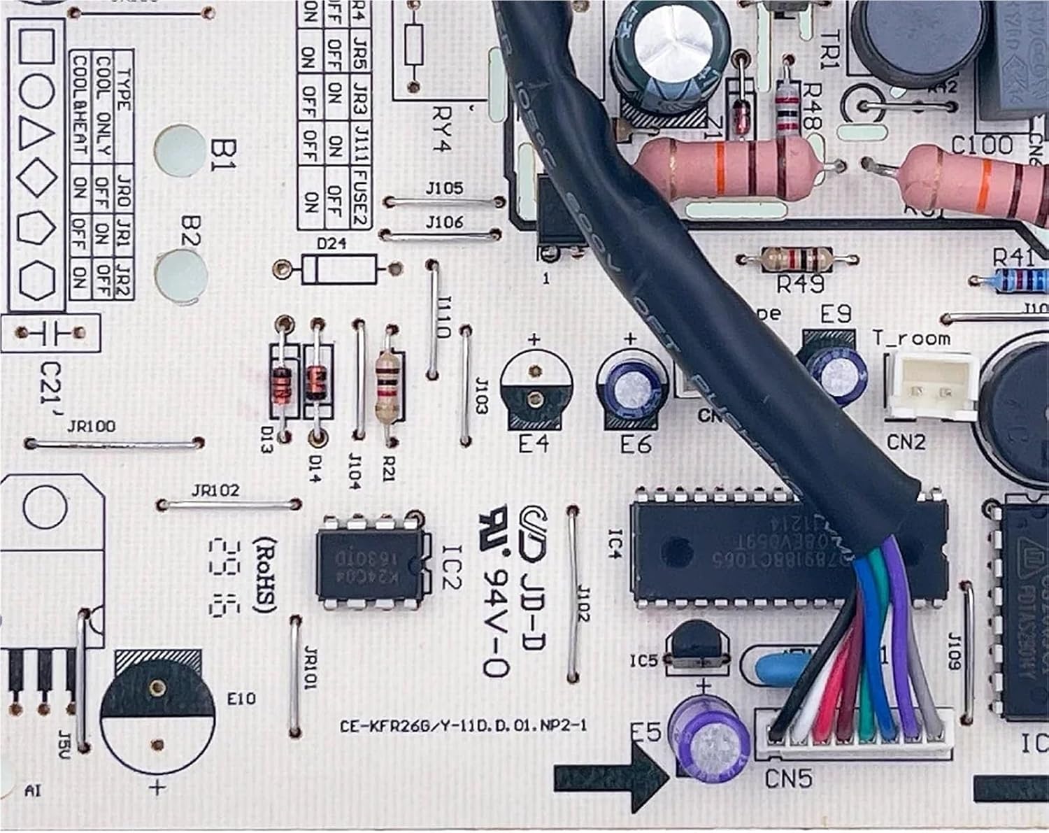
Figure 2: Detailed view of connection points on the control board.
4.4. Post-Installation
- Close Casing: Once all connections are verified, carefully close and secure the indoor unit casing.
- Restore Power: Reconnect the main power supply to the air conditioning unit at the circuit breaker.
- Test Operation: Turn on the air conditioner and test its various functions (e.g., fan speed, cooling mode, temperature settings) to ensure proper operation.
5. Operating Principles
The CE-KFR26G/Y-11D.D.01.NP2-1 control board functions as the central processing unit for the indoor air conditioner. It receives commands from the remote control or thermostat, processes sensor data (e.g., room temperature, coil temperature), and sends signals to control components such as the indoor fan motor, swing motor, and communication module for the outdoor unit. Its adaptive voltage and automatic wind speed adjustment features contribute to efficient and comfortable operation of the air conditioning system.
6. Maintenance
The control board itself requires minimal maintenance. However, to ensure its longevity and reliable operation:
- Keep Dry: Ensure the indoor unit environment remains dry and free from moisture, which can damage electronic components.
- Cleanliness: Periodically inspect the indoor unit for dust accumulation. While cleaning, avoid direct contact with the control board. Use a soft brush or compressed air from a distance if necessary to remove dust from the general area, ensuring power is off.
- Professional Inspection: During routine air conditioner servicing, have a qualified technician inspect the control board for any signs of wear, corrosion, or loose connections.
7. Troubleshooting
If the air conditioner unit is not functioning correctly after replacing the control board, consider the following troubleshooting steps. Always ensure power is disconnected before inspecting internal components.
- No Power: Check the main power supply to the unit and the circuit breaker. Verify all power connections to the control board are secure.
- Incorrect Operation: Double-check all wire connections against your diagrams or photographs. Ensure no wires are loose or connected to the wrong terminals.
- DIP Switch Settings: If applicable, confirm that any DIP switches on the board are set correctly according to the Midea air conditioner's service manual.
- Error Codes: If the air conditioner displays an error code, consult the Midea air conditioner's service manual for the meaning of the code and recommended solutions.
- Professional Assistance: If issues persist, contact a qualified HVAC technician for diagnosis and repair. Complex electrical issues should always be handled by professionals.
8. Specifications
| Attribute | Detail |
|---|---|
| Model Number | CE-KFR26G/Y-11D.D.01.NP2-1 |
| Part Number | 17122000007852 |
| Compatibility | Midea Air Conditioner Indoor Units (Cool models) |
| Brand | LBAXSXP |
| Package Dimensions | 1.18 x 0.79 x 0.39 inches |
| Item Weight | 1.76 ounces |
| Number of Pieces | 1 |
| Key Features | Modular design, Adaptive voltage, Short-circuit protection, Automatic wind speed adjustment |
9. Warranty and Support
For warranty information or technical support regarding the CE-KFR26G/Y-11D.D.01.NP2-1 control board, please contact the seller or manufacturer directly. Keep your purchase receipt and product model information handy when seeking support.
For issues related to the Midea air conditioner unit itself, refer to the original Midea product manual or contact Midea customer service.