1. Introduction
The VECHLINE REGULADOR MPPT 10 is an advanced Maximum Power Point Tracking (MPPT) solar charge controller designed to optimize the power output from your solar panels to efficiently charge your battery bank. This manual provides essential information for the safe installation, operation, and maintenance of your MPPT 10 controller, ensuring optimal performance and longevity.
2. Safety Instructions
Please read and understand all safety instructions before installation and operation. Failure to follow these instructions may result in electric shock, fire, or serious injury.
- Ensure all connections are tight and correct to avoid excessive heat buildup.
- Always connect the battery to the controller first, then the solar panel, and finally the load. Disconnect in the reverse order.
- Do not attempt to disassemble or repair the controller. Contact qualified service personnel.
- Install the controller in a well-ventilated area, away from flammable materials and direct sunlight.
- Wear eye protection when working with batteries.
- Ensure the system voltage (12V/24V) matches the controller's specifications.
3. Package Contents
Verify that all items are present in your package:
- VECHLINE REGULADOR MPPT 10 Solar Charge Controller
- User Manual (this document)
4. Product Overview
The VECHLINE REGULADOR MPPT 10 features a robust design for efficient solar power management. Below is an image of the device with key components highlighted.
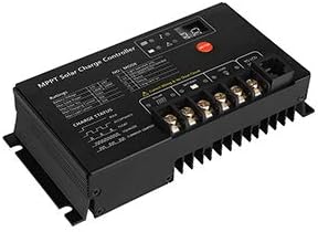
Figure 1: VECHLINE REGULADOR MPPT 10 Solar Charge Controller. This image displays the front and top view of the black MPPT solar charge controller. It features an LCD screen on the top left for displaying system information, three control buttons to the right of the screen, and clearly labeled terminal blocks on the right side for connecting solar panels (PV), batteries (BATTERY), and DC loads (LOAD). The bottom of the unit shows heat sink fins for thermal management. Important safety warnings regarding connection order are also visible on the device's casing.
Key Components:
- LCD Display: Shows real-time system status, including battery voltage, charging current, load status, and error codes.
- Control Buttons: Used for navigating menus, adjusting settings, and viewing different parameters.
- PV Terminals: Connect to your solar panel array.
- Battery Terminals: Connect to your battery bank.
- Load Terminals: Connect to your DC loads (e.g., lights, fans).
- Heat Sink: Dissipates heat generated during operation to maintain optimal performance.
5. Setup and Installation
Proper installation is crucial for the safe and efficient operation of your solar charge controller.
5.1 Mounting Location:
- Mount the controller vertically on a non-flammable surface.
- Ensure adequate air circulation around the controller for cooling.
- Avoid direct sunlight, high temperatures, and moisture.
5.2 Wiring Sequence:
Always follow this connection order to prevent damage to the controller or other components:
- Connect the Battery: Connect the positive and negative terminals of your battery bank to the corresponding battery terminals on the controller. Ensure correct polarity. The controller should power on.
- Connect the Solar Panel: Connect the positive and negative leads from your solar panel array to the corresponding PV terminals on the controller. Ensure correct polarity.
- Connect the DC Load (Optional): Connect your DC loads to the load terminals on the controller. Ensure correct polarity.
To disconnect the system, follow the reverse order: Disconnect load, then solar panel, then battery.
6. Operating Instructions
Once installed, the controller will automatically begin operating. The LCD display provides real-time information about your solar system.
6.1 LCD Display:
The display cycles through various parameters such as:
- Battery Voltage
- Solar Panel Voltage
- Charging Current
- Load Current
- Battery State of Charge (SOC)
- Error Codes (if any)
6.2 Button Functions:
The three buttons typically allow you to:
- Menu/Set Button: Enter/exit menu, confirm settings.
- Up/Down Buttons: Navigate through display screens, adjust values in settings.
Refer to the on-screen prompts for specific button operations related to setting battery types, load control modes, and other configurable parameters.
7. Maintenance
Regular maintenance ensures the longevity and optimal performance of your VECHLINE REGULADOR MPPT 10.
- Check Connections: Periodically inspect all wiring connections for tightness and corrosion. Loose connections can cause overheating and damage.
- Clean the Controller: Keep the controller clean and free of dust and debris. Use a dry cloth to wipe the casing. Ensure ventilation openings are not blocked.
- Inspect Wiring: Check all cables for signs of wear, fraying, or damage. Replace any damaged cables immediately.
- Battery Health: Monitor your battery's health and voltage regularly. Ensure it is properly maintained according to its manufacturer's guidelines.
8. Troubleshooting
If you encounter issues with your controller, refer to the following common problems and solutions:
| Problem | Possible Cause | Solution |
|---|---|---|
| Controller display is off | Battery not connected or low voltage; reverse polarity. | Check battery connections and voltage. Ensure correct polarity. |
| No charging from solar panel | Solar panel not connected; low sunlight; reverse polarity; faulty panel. | Check solar panel connections and polarity. Verify sunlight intensity. Test panel output. |
| Load not working | Load not connected; battery low; overload protection; load output disabled. | Check load connections. Charge battery. Reduce load. Check controller settings for load output. |
| Battery not fully charged | Insufficient solar input; incorrect battery type setting; battery degradation. | Ensure adequate solar panel size and sunlight. Verify battery type setting. Test battery health. |
If the problem persists after attempting these solutions, please contact customer support.
9. Specifications
The following are typical specifications for the VECHLINE REGULADOR MPPT 10. Please refer to your product packaging or the manufacturer's official website for the most accurate and up-to-date specifications.
| Parameter | Value |
|---|---|
| Model | MPPT 10 |
| System Voltage | 12V/24V Auto-recognition |
| Max Charge Current | 10A |
| Max PV Input Voltage | Typically 50V-100V (Varies by model) |
| Max PV Input Power | 12V System: 130W; 24V System: 260W (Approximate) |
| Load Current | 10A |
| Self-consumption | <10mA |
| Operating Temperature | -20°C to +55°C |
| Protection | Overload, Short Circuit, Reverse Polarity, Over-discharge, Overcharge |
10. Warranty and Support
Specific warranty information for the VECHLINE REGULADOR MPPT 10 is not available in this document. Please refer to the warranty card included with your product, the product packaging, or the official VECHLINE website for detailed warranty terms and conditions.
For technical support, troubleshooting assistance beyond this manual, or warranty claims, please contact your retailer or the VECHLINE customer service department.