QUECOO T12-958-STM32
QUECOO T12-958 STM32 V3.1S OLED Soldering Station User Manual
1. Introduction
This user manual provides comprehensive instructions for the safe and effective operation of your QUECOO T12-958 STM32 V3.1S OLED Soldering Station. Please read this manual thoroughly before using the device to ensure proper functionality and to prevent damage or injury. Keep this manual for future reference.
2. Safety Instructions
Observe the following safety precautions to prevent electric shock, fire, or personal injury:
- Electrical Safety: Ensure the power supply voltage matches the requirements of the soldering station (110-240V). Do not operate the station with a damaged power cord or plug. Always connect the station to a grounded outlet.
- Heat Hazard: Soldering iron tips reach high temperatures (50°C-480°C). Avoid direct contact with the tip and allow it to cool completely before handling or storing. Use a heat-resistant stand for the soldering iron when not in use.
- Ventilation: Solder fumes can be harmful. Always work in a well-ventilated area or use a fume extractor.
- Personal Protective Equipment: Wear safety glasses to protect your eyes from solder splatter.
- Flammable Materials: Keep flammable materials away from the soldering area.
- Children and Unauthorized Users: Keep the soldering station out of reach of children and individuals unfamiliar with its operation.
- Maintenance: Disconnect power before performing any maintenance or cleaning.
3. Product Components
The QUECOO T12-958 Soldering Station package typically includes the following items:
- T12-958 Soldering Station Unit
- 907 Soldering Handle
- T12 Series Iron Tips (various types)
- US Power Plug (or regional equivalent)
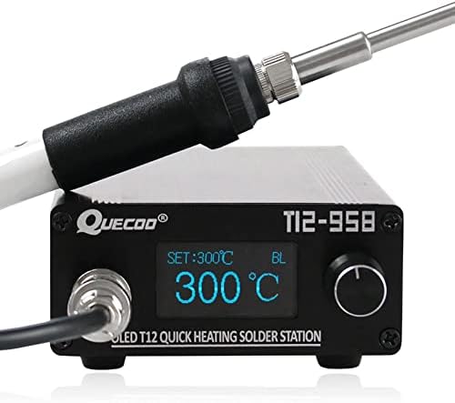
Figure 3.1: QUECOO T12-958 Soldering Station with connected iron handle.

Figure 3.2: Example of a T12 Lead-free Iron Tip and handle.
4. Product Features
The QUECOO T12-958 Soldering Station offers the following key features:
- Rapid Heating: Heats up to 300°C in approximately 8 seconds with quick thermal recovery.
- Wide Temperature Range: Output temperature adjustable from 50°C to 480°C.
- OLED Display: Clear 1.3-inch OLED screen for temperature display and menu navigation.
- STM32 V3.1S Controller: Advanced control system for precise temperature management.
- Auto-Sleep/Standby: Automatic sleep and standby functions to conserve energy and prolong tip life.
- Boost Function: Temporarily increases temperature for demanding soldering tasks.
- Durable Construction: Features an aluminum alloy station case.
- Power Output: 72W nominal, with a maximum output of 120W.

Figure 4.1: Overview of T12-958 Soldering Station features.
5. Product Overview (Physical)
Familiarize yourself with the physical components and interfaces of the soldering station.
5.1 Front Panel
- Handle Interface: Connector for the soldering iron handle.
- OLED Display: Shows current temperature, set temperature, and menu options.
- Encoder Knob: Used for adjusting temperature and navigating menus. Rotate to change values, press to confirm or enter menus.
5.2 Rear Panel
- Power Switch: On/Off switch for the unit.
- AC Interface: Main power input (AC110-240V).
- Fuse Holder: Contains the protective fuse.
- Ground Terminal: For external grounding connection.
- DC Input: Optional DC 24V 4A power input.

Figure 5.1: Front and Rear Panel Interfaces.

Figure 5.2: Physical dimensions of the soldering station.
6. Setup
Follow these steps to set up your soldering station:
- Connect the Soldering Handle: Insert the connector of the 907 soldering handle into the handle interface on the front panel of the station. Ensure it is securely fastened.
- Insert Soldering Tip: Carefully insert the desired T12 iron tip into the soldering handle. Ensure the tip is fully seated and the retaining nut (if present) is tightened to avoid poor contact.
- Power Connection: Connect the provided power cord to the AC interface on the rear panel of the station, then plug it into a grounded electrical outlet. Alternatively, if using DC power, connect a 24V 4A DC power supply to the DC input.
- Grounding (Recommended): For enhanced safety and performance, connect an external ground wire from the ground terminal on the rear panel to a reliable earth ground.
- Placement: Place the soldering station on a stable, heat-resistant surface, away from flammable materials. Ensure adequate ventilation.
7. Operating Instructions
7.1 Powering On/Off
Flip the power switch on the rear panel to the 'ON' position to power on the station. The OLED display will illuminate. To power off, flip the switch to 'OFF'.
7.2 Temperature Adjustment
Rotate the encoder knob on the front panel to adjust the target temperature. The set temperature will be displayed on the OLED screen. The station will rapidly heat to the set temperature.
7.3 Menu Navigation
Press the encoder knob to enter the main settings menu. Rotate the knob to scroll through menu options and press again to select an option. Rotate to change values within a setting, and press to confirm.

Figure 7.1: OLED Display Menu Options.
7.4 Sleep and Standby Functions
The station features automatic sleep and standby modes to preserve tip life and save energy. These settings can be configured in the menu.
- Sleep Mode: After a user-defined period of inactivity (e.g., 30 minutes default), the station will enter sleep mode, reducing the tip temperature to a lower value (e.g., 150°C). Shaking the iron or pressing the encoder will wake it up to the previous working temperature.
- Standby Mode: If inactivity continues beyond the sleep period, the station may enter a deeper standby mode.

Figure 7.2: Setting Sleep Time.
7.5 Boost Function
The Boost function allows for a temporary increase in tip temperature, useful for soldering larger joints or components that require more heat. This function can be configured in the settings menu.
- Activation: Access the Boost menu via the encoder knob.
- Settings: Adjust the Boost temperature and duration. Default settings are typically 50°C increase for 5 minutes.

Figure 7.3: Activating and Setting Boost Function.
7.6 Tip Selection
The station requires you to select the specific T12 tip type being used for optimal performance. Each tip has a unique code label. Navigate to the 'Tip' setting in the menu to enable or select the correct tip type.
Important Note: When using a new T12 iron tip for the first time, it may display an 'ERROR' message initially. This is normal. After heating for 5-20 minutes, it should return to normal operation. Ensure the tip's retaining nut is tightened to avoid poor contact.

Figure 7.4: Display States (Error, Normal, Boost).
8. Maintenance
8.1 Soldering Tip Care
- Tinning: Always tin the tip with a thin layer of solder before and after use to prevent oxidation.
- Cleaning: Use a damp sponge or brass wool to clean the tip regularly during soldering. Avoid abrasive materials.
- Temperature: For optimal tip life, avoid operating the iron above 380°C for extended periods unless necessary.
- Storage: Store tips properly to prevent damage and oxidation.
8.2 Station Cleaning
Wipe the station's exterior with a soft, dry cloth. Do not use harsh chemicals or solvents. Ensure the unit is unplugged and cool before cleaning.
9. Troubleshooting
- "ERROR" Message on Display: This typically indicates a non-plugged iron tip or poor contact. Ensure the tip is correctly inserted and the retaining nut is tightened. For new tips, allow 5-20 minutes for initial heating and stabilization.
- Tip Not Heating or Intermittent Heating: Check the connection of the soldering handle to the station. Ensure the T12 tip is fully seated within the handle and making good contact. Loose internal contacts within the handle can cause this; try rotating the tip slightly.
- No Ground Connection at Tip: If you suspect a grounding issue, verify the external ground connection to the station. Internally, ensure proper connection between the ground jack and the power cord ground. The tip's ground is typically connected to the 0V side of the internal power supply.
- Iron Enters Sleep Mode Too Frequently: Adjust the sleep delay time in the settings menu. If the motion sensor is overly sensitive, ensure the iron is placed on a stable surface and not subject to vibrations.
- Unable to Select Tip Type: Navigate to the 'Tip' menu. If certain tip types are disabled, enable them. If the unit is stuck on a specific tip type, consult the manual's detailed menu navigation section or perform a factory reset if necessary.
10. Specifications
| Feature | Specification |
|---|---|
| Model Number | T12-958-STM32 |
| Input Voltage | 110-240V AC |
| Output Power | 72W (Max 120W) |
| Temperature Range | 50°C - 480°C |
| Temperature Stability | ±5°C |
| Display Type | OLED |
| Controller | STM32 V3.1S (HW: 3.10, SW: 3.1S) |
| Item Weight | 0.6 Kilograms (1.32 pounds) |
| Package Dimensions | 7.09 x 3.94 x 3.94 inches |
| UPC | 742404654525 |
11. Warranty and Support
For warranty information or technical support, please refer to the documentation provided with your purchase or contact the manufacturer directly. Keep your purchase receipt as proof of purchase.
Related Documents - T12-958-STM32
 |
QUECOO T12-958 Soldering Station User Guide User guide and operational instructions for the QUECOO T12-958 OLED soldering station, covering sleep settings, display troubleshooting, and boost function usage. |
 |
QUECOO T12-958 Soldering Station User Manual User manual for the QUECOO T12-958 OLED soldering station, covering setup, display operation, safety warnings, and the boost function. |
 |
QUECOO T85 Smart Soldering Iron User Manual Comprehensive user manual for the QUECOO T85 Smart Portable Electric Soldering Iron, detailing features, operation, power selection, maintenance, safety instructions, and warranty terms. |
 |
T12 Soldering Iron Product Manual - Shenzhen Weishang Power Network Technology Co., Ltd Official product manual for the T12 Soldering Iron by Shenzhen Weishang Power Network Technology Co., Ltd. Includes safety warnings and instructions for use. |
 |
Quecoo T12-958 HW v3.20 Schematic Diagram Detailed traced schematic diagram for the Quecoo T12-958 soldering station hardware version 3.20, Release V04. Includes sections for power generation, ADC, PWM, display, buzzer, temperature sensing, handle interface, RTC, encoder, and headers, all centered around the STM32F103C8T6 microcontroller. |
Ask a question about this manual
Ask about setup, troubleshooting, compatibility, parts, safety, or missing instructions. Manuals+ will review the question and use this page’s manual context to help answer it.