RQG LCR-P1
RQG LCR-P1 Transistor and Component Tester User Manual
Model: LCR-P1
1. Introduction
The RQG LCR-P1 Transistor and Component Tester is a versatile and high-precision instrument designed for the detection and analysis of various electronic components. It is suitable for electronic engineers, technicians, and enthusiasts. This device features a color screen for multi-parameter measurement, automatic identification of component types, and pin arrangements, streamlining the testing process and improving efficiency.
This manual provides essential information for the safe and effective use of your LCR-P1 tester, including setup, operation, maintenance, and technical specifications.
2. Package Contents
Verify that all items are present in the package:
- 1 x RQG LCR-P1 Transistor Capacitor Tester
- 1 x Test Board (for SMD components)
- 3 x Test Hooks
- 1 x Data Cable (for charging and data transmission)
- 1 x User Manual (this document)

Image 2.1: The LCR-P1 tester shown with its test board, test hooks, and data cable.
3. Setup and Initial Use
3.1 Charging the Device
The LCR-P1 is equipped with a built-in 300mAh lithium battery. Before first use, or when the battery indicator shows low charge, connect the device to a standard USB power source using the provided data cable. The charging indicator will show the charging status.
3.2 Connecting Test Components
The tester offers multiple ways to connect components:
- Standard Test Socket: For through-hole components, insert the component leads into the appropriate numbered slots (1, 2, 3) on the main test socket.
- SMD Test Board: For surface-mount devices (SMD), attach the included test board to the designated connector. Place the SMD component onto the pads of the test board.
- Test Hooks: For larger components or in-circuit testing (with power off), use the provided test hooks. Connect the hooks to the corresponding pins on the main test socket (1, 2, 3).
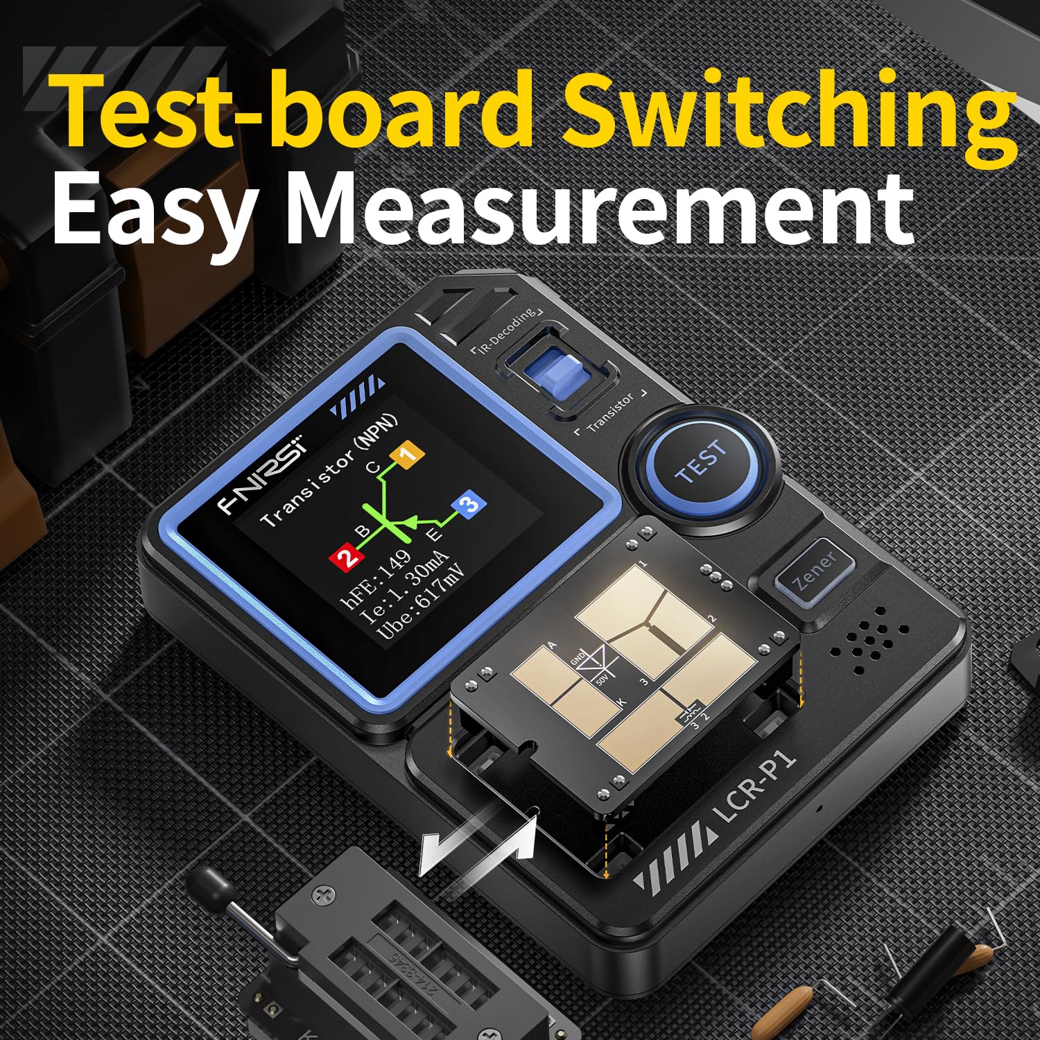
Image 3.1: The interchangeable test board for SMD components, demonstrating flexible measurement options.
4. Operating Instructions
4.1 Basic Component Testing
- Ensure the device is powered on.
- Connect the component to be tested using the appropriate method (test socket, SMD board, or test hooks).
- Press the TEST button.
- The LCR-P1 will automatically identify the component type, detect its pinout, and display relevant parameters on the 1.44-inch color screen.

Image 4.1: The LCR-P1 screen displaying the results of a transistor test, including pin configuration and parameters.
4.2 Supported Component Types and Parameters
The LCR-P1 can measure and analyze a wide range of components:
- Transistors: NPN, PNP, Triode, MOS, Field-Effect Transistors (FETs), IGBT. Displays hFE, base-emitter voltage, collector current, etc.
- Diodes: Standard diodes, Zener diodes (0.01-4.5V, 0.01-32V). Displays forward voltage drop.
- Capacitors: 25µF - 100mF. Displays capacitance, ESR (Equivalent Series Resistance).
- Resistors: 0.01Ω - 50MΩ. Displays resistance value.
- Inductors: 10µH - 1000µH. Displays inductance value.
- SCRs: Unidirectional/Bidirectional SCRs (Turn-on voltage <5V, gate trigger current <6mA).
4.3 Battery Testing
The device can test batteries within the range of 0.1V to 4.5V. Connect the battery to the appropriate test points, and the tester will display its voltage.
4.4 Infrared (IR) Decoding
The LCR-P1 supports NEC protocol infrared signal decoding. Point an infrared remote control towards the IR receiver on the tester and press a button. The device will display the decoded infrared code, which is useful for testing and maintaining remote control equipment.

Image 4.2: The LCR-P1 demonstrating its infrared decoding capability with a remote control.
4.5 Safety Feature: Anti-Burn Protection
The LCR-P1 incorporates an anti-burn protection mechanism. This feature automatically discharges undischarged capacitors upon insertion, helping to prevent accidental damage to the device or the component being tested.

Image 4.3: Visual representation of the anti-burn protection feature, designed for safe measurement.
5. Maintenance
- Cleaning: Use a soft, dry cloth to clean the device. Do not use abrasive cleaners or solvents.
- Storage: Store the LCR-P1 in a cool, dry place away from direct sunlight and extreme temperatures.
- Battery Care: For optimal battery life, avoid fully discharging the battery frequently. Recharge the device regularly, especially if stored for extended periods.
- Firmware Updates: The device supports firmware upgrades via the data cable. Refer to the manufacturer's website for available updates and instructions.
6. Troubleshooting
| Problem | Possible Cause | Solution |
|---|---|---|
| Device does not power on. | Low or depleted battery. | Connect the device to a USB power source using the provided data cable and allow it to charge. |
| Inaccurate or inconsistent readings. | Poor component connection; component outside measurement range; component damage. | Ensure component leads are firmly inserted or connected. Verify the component is within the tester's specified measurement range. Test with a known good component. |
| "Unknown or No Element" displayed. | Component not properly connected; component is faulty; component type not supported. | Re-insert the component. Check for damage. Refer to the supported component list in this manual. |
| IR decoding not working. | Remote control not using NEC protocol; remote control battery low; incorrect aiming. | Ensure the remote control uses the NEC protocol. Check remote control batteries. Aim the remote control directly at the IR receiver on the LCR-P1. |
7. Specifications
| Parameter | Value |
|---|---|
| Model | LCR-P1 |
| Display Screen | 1.44-inch Color Screen |
| Battery Capacity | 300mAh Lithium Battery |
| Power Source | Battery Powered (USB Rechargeable) |
| Size | Approx. 2.8 x 3.4 x 1.1 inches |
| Min. Operating Voltage | 0.01 Volts (DC) |
| Resistor Measurement Range | 0.01Ω - 50MΩ |
| Capacitor Measurement Range | 25µF - 100mF |
| Inductor Measurement Range | 10µH - 1000µH |
| Diode Forward Voltage Drop | <4.5V |
| Zener Diode Measurement Range | 0.01-4.5V, 0.01-32V |
| Battery Test Range | 0.1V - 4.5V |
| Infrared Decoding | NEC Protocol |

Image 7.1: The compact size of the LCR-P1, emphasizing its portability.
8. Support and Contact Information
For technical support, warranty inquiries, or further assistance, please contact your retailer or the manufacturer, RQG. Refer to your purchase documentation for specific contact details.
You may also visit the official RQG website for product updates and additional resources.
Ask a question about this manual
Ask about setup, troubleshooting, compatibility, parts, safety, or missing instructions. Manuals+ will review the question and use this page’s manual context to help answer it.