1. Introduction
This manual provides essential information for the safe and correct installation, operation, and maintenance of the Generic Fuel Pump Assembly, model 31110-26510. Please read these instructions thoroughly before proceeding with any installation or service to ensure proper function and prevent damage or injury. This fuel pump assembly is designed as a replacement part for specific Hyundai Santa Fe I models.
2. Safety Information
Working with fuel systems involves inherent risks. Adhere to all safety precautions to prevent accidents.
- Professional Installation Recommended: Installation of this component should ideally be performed by a qualified automotive technician.
- Disconnect Battery: Always disconnect the vehicle's negative battery terminal before beginning any work on the fuel system.
- Relieve Fuel System Pressure: Before disconnecting any fuel lines, ensure the fuel system pressure is safely relieved according to the vehicle manufacturer's service manual.
- Fuel is Flammable: Work in a well-ventilated area, away from open flames, sparks, or other ignition sources. Have a fire extinguisher readily available.
- Wear Personal Protective Equipment (PPE): Use safety glasses, gloves, and appropriate protective clothing to prevent contact with fuel and other automotive fluids.
- Secure Vehicle: Ensure the vehicle is properly supported on jack stands or a lift before working underneath it.
- Handle with Care: Avoid dropping or damaging the fuel pump assembly. Damage can lead to malfunction or leaks.
3. Product Overview
The Generic Fuel Pump Assembly (31110-26510) is a complete unit designed to replace the original fuel pump in compatible vehicles. It includes the electric fuel pump, fuel level sending unit, and filter sock, all integrated into a single module for efficient fuel delivery from the tank to the engine.
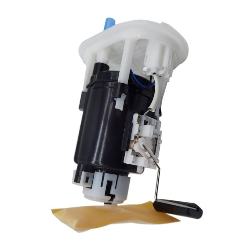
Figure 1: Overall view of the Generic Fuel Pump Assembly, showing the main pump body, fuel level float arm, and electrical connectors.
3.1. Compatibility
This fuel pump assembly is compatible with the following vehicle models and OEM part numbers:
| Vehicle Model | Years | Engine Displacement | OEM Part Numbers |
|---|---|---|---|
| Hyundai SANTA FÉ I (SM) | 2001-2006 | 2.4L 16V (G4JS) | 31110-26510, 3111026510DS |
| KIA (Reference) | 3111026510, 3111026510DS |
Cross-reference numbers include: CAMBIARE: VE523755, ELTA AUTOMOTIVE: XFP9392, FISPA: 72815, FUELPARTS: FP5592, HOFFER: 7507439, INTERMOTOR: 39483, EFP833, LFP654, MEAT & DORIA: 77439, SIDAT: 72815, WILMINK GROUP: WG1407843.
4. Installation Guide
The following steps provide a general guide for installation. Always refer to your vehicle's specific service manual for detailed instructions and torque specifications.
4.1. Pre-Installation Checks
- Verify that the new fuel pump assembly matches the old unit in terms of connections and physical dimensions.
- Inspect the fuel tank for any debris or contamination. Clean if necessary.
- Ensure all necessary tools and replacement parts (e.g., new fuel tank gasket, fuel line clips) are available.
4.2. Installation Steps
- Prepare Vehicle: Park the vehicle on a level surface, engage the parking brake, and disconnect the negative battery terminal.
- Relieve Fuel Pressure: Follow the vehicle manufacturer's procedure to safely relieve fuel system pressure.
- Access Fuel Pump: Locate the fuel pump access panel, typically under the rear seat or in the trunk. Remove any carpeting or covers.
- Disconnect Fuel Lines and Electrical Connector: Carefully disconnect the fuel lines and the electrical connector from the old fuel pump module. Be prepared for residual fuel leakage.
- Remove Old Fuel Pump: Unscrew or unclip the retaining ring/lock nut that secures the fuel pump assembly to the fuel tank. Carefully lift the old assembly out of the tank, being mindful of the fuel level float arm.
- Install New Fuel Pump: Install a new fuel tank gasket. Carefully insert the new Generic Fuel Pump Assembly into the fuel tank opening, ensuring the float arm moves freely and does not snag. Align the assembly correctly and secure it with the retaining ring/lock nut.
- Reconnect: Reconnect the fuel lines and the electrical connector. Ensure all connections are secure and free of leaks.
- Reconnect Battery: Reconnect the negative battery terminal.
- Initial Test: Turn the ignition key to the 'ON' position (without starting the engine) for a few seconds, then turn it 'OFF'. Repeat this a few times to prime the fuel system and build pressure. Check for any fuel leaks around the new pump assembly.
- Start Engine: Start the engine and check for smooth operation and any warning lights.
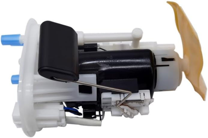
Figure 2: Side view of the fuel pump assembly, highlighting the integrated fuel filter sock at the bottom, which should be submerged in fuel.
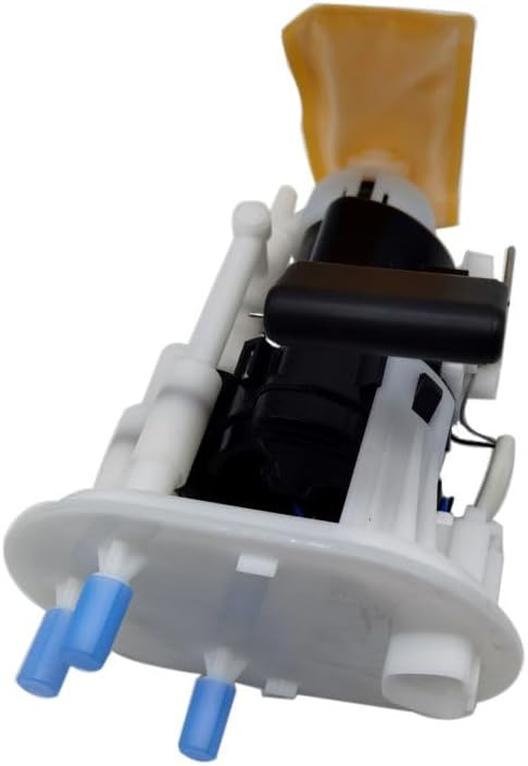
Figure 3: Top view of the fuel pump assembly, showing the electrical connector and fuel outlet ports. Ensure these are properly connected during installation.
5. Operation
Once properly installed, the fuel pump assembly will operate automatically as part of the vehicle's fuel delivery system. It is designed to maintain consistent fuel pressure and flow to the engine. The fuel level sending unit will accurately report the fuel tank level to the vehicle's gauge.

Figure 4: Fuel pump assembly showing the float arm and fuel level sensor. This component accurately measures the fuel level in the tank.
6. Maintenance
The fuel pump assembly itself is generally considered a non-serviceable component. However, proper fuel system maintenance can extend its lifespan and ensure optimal performance.
- Fuel Filter: While this assembly includes an integrated filter sock, some vehicles may have an additional in-line fuel filter. Refer to your vehicle's service schedule for recommended replacement intervals for all fuel filters.
- Fuel Quality: Use high-quality fuel from reputable sources to prevent contaminants from clogging the fuel pump and filter.
- Avoid Running on Low Fuel: Regularly running the fuel tank to near empty can cause the fuel pump to overheat as it relies on fuel for cooling and lubrication.
7. Troubleshooting
If you experience issues after installation, consider the following common problems and solutions. If problems persist, consult a qualified technician.
| Problem | Possible Cause | Solution |
|---|---|---|
| Engine cranks but does not start | No fuel pressure, electrical connection issue, clogged fuel filter | Check electrical connections, verify fuel pump operation (listen for hum), check fuel pressure, inspect fuel filter. |
| Engine stalls or misfires | Insufficient fuel pressure/flow, contaminated fuel | Check fuel pressure, inspect fuel filter, consider draining and replacing fuel if contaminated. |
| Fuel leak around assembly | Improperly seated gasket, loose retaining ring, damaged fuel line | Re-check gasket seating, tighten retaining ring, inspect fuel lines and connections for damage. |
| Inaccurate fuel gauge reading | Fuel level sending unit malfunction, float arm obstruction, electrical issue | Verify float arm movement, check electrical connection to sending unit, inspect wiring. |
8. Specifications
- Part Number: 31110-26510
- Manufacturer Part Number: LMEM545C125FCD9B7DD266A77BF9E0FEFB5A
- Brand: Generic
- Compatible Vehicles: Hyundai Santa Fe I (SM) 2.4L 16V (2001-2006)
- OEM Cross-Reference: 3111026510, 3111026510DS (Hyundai/KIA) and others listed in Section 3.1.
9. Warranty and Support
For warranty information or technical support, please refer to the terms provided by your retailer or contact the manufacturer directly. Keep your purchase receipt as proof of purchase.