1. Introduction
This manual provides comprehensive instructions for the installation, operation, and maintenance of the LCWLYOBM KWS-DC200 DC Voltmeter Ammeter Power Energy Meter. This device is designed to accurately measure DC voltage, current, power, energy (Wh), ampere-hour (Ah), timing, and temperature in various electrical systems. Please read this manual thoroughly before use to ensure proper functionality and safety.
2. Product Overview
The KWS-DC200 is a multifunctional DC tester featuring a clear LED digital display. It integrates several measurement capabilities into a compact unit, making it suitable for monitoring battery systems, solar setups, and other DC power applications.

Figure 2.1: LCWLYOBM KWS-DC200 DC Multifunction Tester with connection wires.
The 100A variant includes an external shunt for high current measurement, ensuring accuracy and safety.
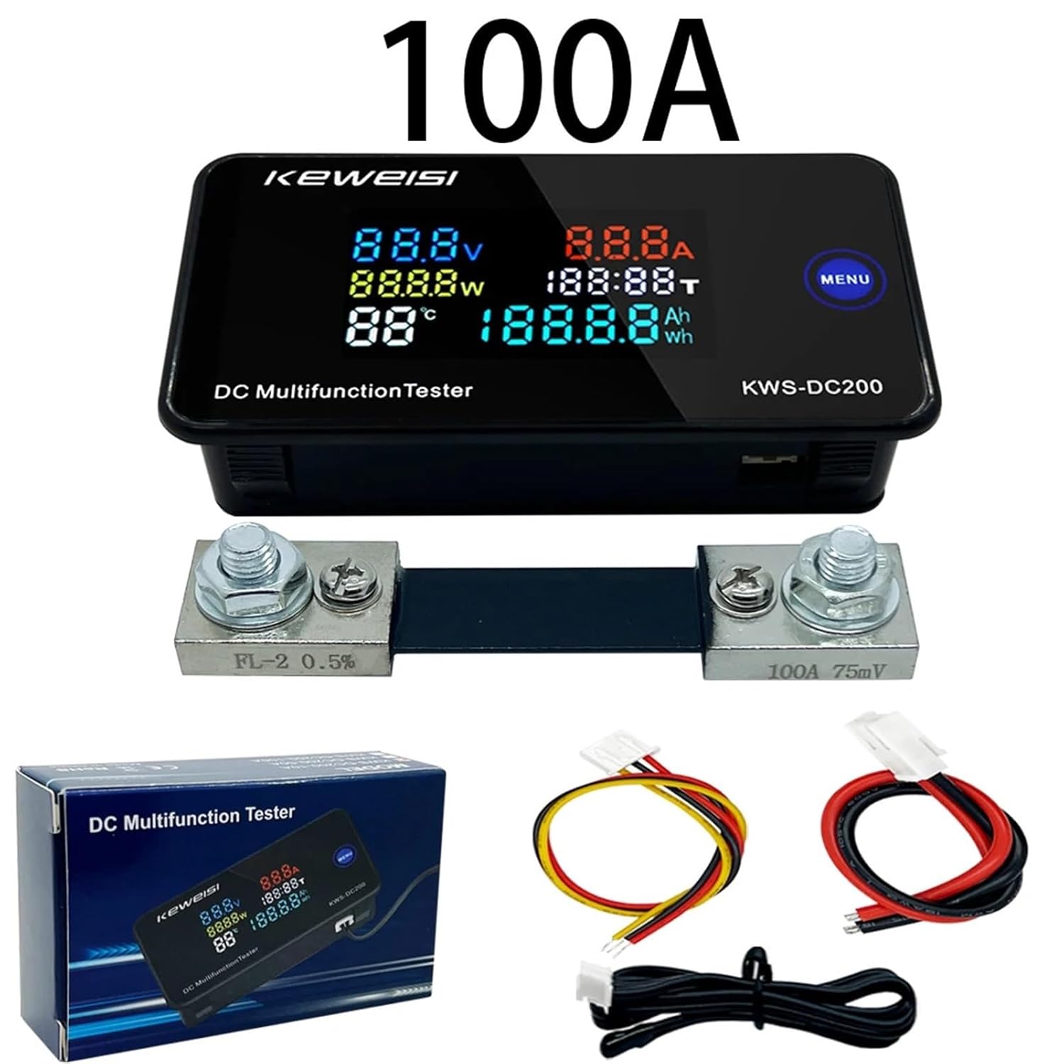
Figure 2.2: KWS-DC200 100A model, showing the main unit, external shunt, and connection cables.
3. Specifications
The following specifications apply to the KWS-DC200 100A model:
- Power Supply Voltage: 8-120V DC
- Test Voltage Range: 0-200V DC
- Current Measurement Range: 0-100A DC
- Power Measurement Range: 0-20000W
- Ampere-hour (Ah) Range: 0-19999Ah
- Watt-hour (Wh) Range: 0-19999Wh
- Timing Range: 0-200H
- Temperature Range: -9°C to 99°C
Physical Dimensions:

Figure 3.1: Dimensions of the KWS-DC200 main unit.

Figure 3.2: Dimensions of the 100A external shunt.
4. Setup and Wiring
Correct wiring is crucial for accurate measurements and safe operation. The KWS-DC200 supports two power supply methods: independent power supply and direct power supply.
4.1 Wiring Diagrams
Refer to the following diagrams for proper connection. The 100A model requires an external shunt for current measurement.

Figure 4.1: Wiring diagrams for 10A, 50A, and 100A models. For the 100A model, ensure the external shunt is correctly installed in series with the load.
4.2 Power Supply Options
- Independent Power Supply: The meter can be powered by a separate DC power source (8-120V) while measuring a different DC voltage (0-200V). This method is recommended for precise measurements, especially when the measured voltage is outside the meter's direct power supply range or when isolating the meter's power from the measured circuit.
- Direct Power Supply: The meter can draw power directly from the circuit it is measuring, provided the voltage is within 8-120V DC. In this configuration, the meter's power input is connected to the same points as the voltage measurement.
4.3 Sensor Port
The device includes a sensor port, typically for temperature measurement. Connect the provided temperature sensor to this port.

Figure 4.2: Location of the sensor port on the KWS-DC200 unit.
5. Operating Instructions
The KWS-DC200 features a clear LED display and a single 'MENU' button for operation.
5.1 Display Modes
The meter continuously displays voltage (V), current (A), power (W), and temperature (°C). The lower right section of the display can cycle between Ampere-hour (Ah) and Watt-hour (Wh) readings.
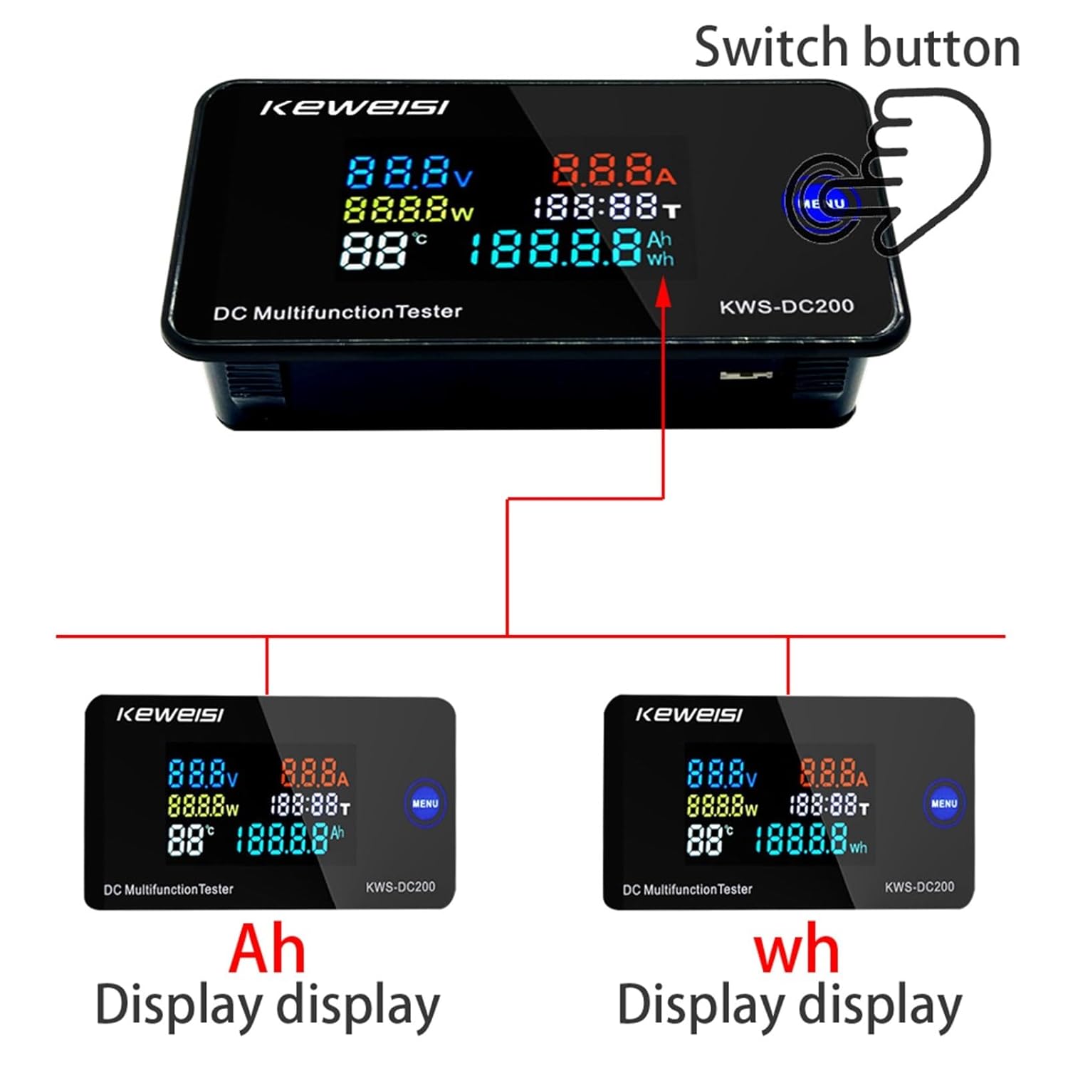
Figure 5.1: Display modes for Ampere-hour (Ah) and Watt-hour (Wh).
5.2 MENU Button Functions
- Short Press: Click the 'MENU' button to cycle through the display of Ampere-hour (Ah) and Watt-hour (Wh) data.
- Long Press (3 seconds): Press and hold the 'MENU' button for 3 seconds to reset the accumulated timing, Ampere-hour (Ah), and Watt-hour (Wh) data to zero. This is useful for starting new measurement cycles.
6. Calibration
The KWS-DC200 is equipped with numerical calibration functions for current and voltage, accessible via adjustment screws on the circuit board. These are typically factory-calibrated, but can be fine-tuned if necessary.
Figure 6.1: Location of Current (A) and Voltage (V) calibration screws.
- Current Calibration Screw: Adjust this screw to fine-tune the current reading. Use a known accurate ammeter for comparison.
- Voltage Calibration Screw: Adjust this screw to fine-tune the voltage reading. Use a known accurate voltmeter for comparison.
Zero Current Value: To zero the current value, press and hold the designated zero button (often integrated with the MENU button or a separate internal button) for 3 seconds. This ensures accurate current measurement when no load is present.
7. Maintenance
- Cleaning: Use a soft, dry cloth to clean the display and casing. Avoid abrasive cleaners or solvents.
- Storage: Store the device in a dry, dust-free environment away from direct sunlight and extreme temperatures.
- Inspection: Periodically check all wiring connections for tightness and signs of wear or corrosion.
8. Troubleshooting
- No Display: Check the power supply connections. Ensure the input voltage is within the 8-120V range.
- Incorrect Readings: Verify all wiring connections are correct according to the diagrams. If current or voltage readings are consistently off, consider performing a calibration as described in Section 6.
- Current Not Displaying: Ensure the external shunt (for 50A/100A models) is correctly installed in series with the load and the meter's current sensing wires are properly connected to the shunt.
- Reset Function Not Working: Ensure you are pressing and holding the 'MENU' button for the full 3 seconds required for the reset function.
9. Warranty and Support
For warranty information and technical support, please refer to the product packaging or contact your retailer. Keep your purchase receipt as proof of purchase.