ATNEDCVH WG502F
ATNEDCVH WG502F Ethernet Range Extender Repeater Kit User Manual
Extend Your Network Reach with Reliability and Performance
1. Introduction
This user manual provides detailed instructions for the installation, operation, and maintenance of your ATNEDCVH WG502F Ethernet Range Extender Repeater Kit. This kit is designed to extend Ethernet LAN range over long distances using Cat5e/6/6e RJ45 network cables or twisted pair cables, making it ideal for various network transmission systems.
Package Contents
Please verify that all items are present in your package:
- WG502F Ethernet Extender * 1 pair (transmitter & receiver)
- DC 12V power adapter * 2pcs
- User guide * 1pcs

Image: The ATNEDCVH WG502F Ethernet Extender Repeater Kit, consisting of a transmitter and a receiver unit. Each unit is compact and features various ports and indicator lights.
2. Product Overview
Key Features
- Extended Transmission Distance: Max 6560FT (2000m) over Cat5e/6/6e network cable; Max 3280FT (1000m) over RVV twisted pair cable.
- Wide Application: Ideal for security monitoring systems, elevator video network coverage, multimedia network systems, industrial automation control, and real-time advertising playback systems.
- Integrated Power Output: Each unit includes an additional terminal block providing 10-60V/1A power output to connected devices, reducing the need for separate power sources at remote locations.
- Robust Design: Exquisite and compact all-metal shell for efficient heat dissipation and stable operation.
- Non-PoE: Both transmitter and receiver units require separate DC power adapters for operation.
Interfaces and Indicators
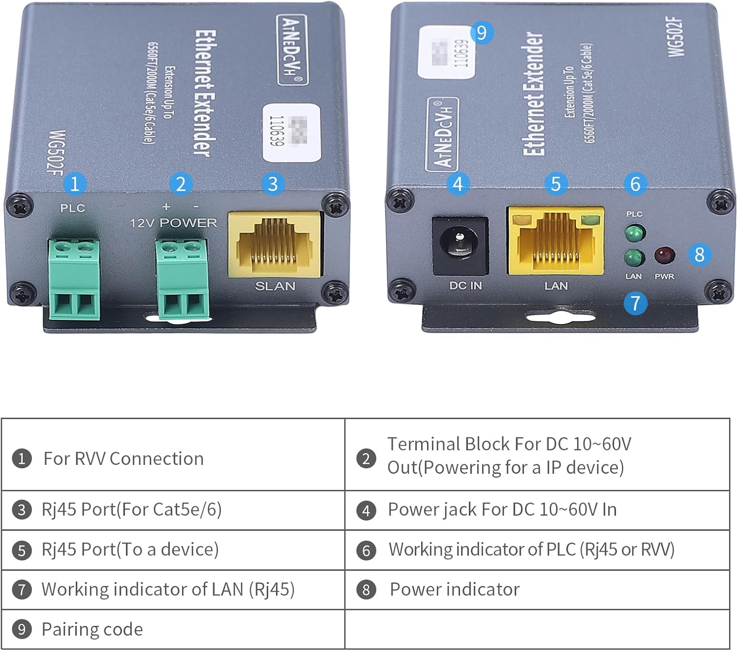
Image: Detailed view of the WG502F units, highlighting the various ports and indicator lights with corresponding numerical labels.
| No. | Label | Description |
|---|---|---|
| 1 | PLC | Terminal Block for RVV Connection |
| 2 | 12V POWER | Terminal Block for DC 10-60V Out (Powering for an IP device) |
| 3 | SLAN | RJ45 Port (For Cat5e/6/6e connection) |
| 4 | DC IN | DC 12V Power Jack (10-60V wide voltage input supported) |
| 5 | LAN | RJ45 Port (To a network device like a switch or NVR) |
| 6 | PLC Indicator | Working indicator for PLC (RVV cable) connection |
| 7 | LAN Indicator | Working indicator for LAN (RJ45) connection |
| 8 | PWR Indicator | Power indicator |
| 9 | Pairing Code | Unique identifier for pairing units |
3. Setup and Installation
Before You Begin
- Ensure you have the necessary network cables (Cat5e/6/6e or RVV twisted pair) of appropriate length.
- Confirm that your network devices (e.g., IP cameras, NVRs, switches) are compatible with Ethernet connectivity.
- The product does not support PoE (Power over Ethernet). Both the transmitting and receiving ends require a DC power adapter for power supply.
Connection Steps
Follow these steps to set up your Ethernet Extender Repeater Kit:
- Connect Power: Connect one DC 12V power adapter to the 'DC IN' port of the first WG502F unit (Transmitter). Connect the second DC 12V power adapter to the 'DC IN' port of the second WG502F unit (Receiver). The PWR indicator light should illuminate.
- Connect Network Devices:
- For the Transmitter unit: Connect your source network device (e.g., NVR, switch) to the 'LAN' port using a standard RJ45 Ethernet cable.
- For the Receiver unit: Connect your remote network device (e.g., IP camera) to the 'LAN' port using a standard RJ45 Ethernet cable.
- Connect Extender Units:
- Using Cat5e/6/6e Cable: Connect the 'SLAN' port of the Transmitter unit to the 'SLAN' port of the Receiver unit using a Cat5e/6/6e RJ45 network cable.
- Using RVV Twisted Pair Cable: Connect the 'PLC' terminal block of the Transmitter unit to the 'PLC' terminal block of the Receiver unit using a 2-core RVV twisted pair cable. Ensure correct polarity (+ to + and - to -).
- Verify Connection: Once connected, the PLC or LAN indicator light (depending on the cable type used for extension) on both units should illuminate, indicating a successful link. The LAN indicator on each unit will also show activity when data is being transmitted.
- Powering External Devices (Optional): If you need to power a remote device (e.g., an IP camera) from the extender, connect the device's power input to the '12V POWER' terminal block on the Receiver unit. The voltage provided will match the input voltage of the DC power adapter connected to the extender (e.g., 12V if using the default 12V adapter).

Image: A visual representation of the connection setup, showing how the WG502F units connect to a switch, NVR, and camera using both Ethernet and 2-core RVV cables, along with power adapters.
4. Operation
Basic Operation
Once properly installed and powered, the WG502F Ethernet Extender Repeater Kit operates automatically. It transparently extends your Ethernet network, allowing data transmission between your local network and remote devices over long distances.
- The PWR indicator light should be solid green when the unit is powered on.
- The PLC indicator light will be solid green when a stable connection is established over the RVV cable.
- The LAN indicator light will be solid green when an Ethernet link is established and will blink to indicate data activity.
Powering Network Devices (10-60V Output)
The WG502F units are equipped with a terminal block for providing power to external network devices. This feature is particularly useful for powering remote IP cameras or other low-power devices directly from the extender unit, simplifying wiring at the remote end.
- The voltage supplied by the '12V POWER' terminal block is equal to the input voltage of the DC power adapter connected to the extender unit. For example, if you use the default 12V power adapter, the output will be 12V.
- Ensure that the device you intend to power is compatible with the voltage and current (up to 1A) supplied by the extender. If your device requires a different voltage, you will need to use a power adapter with the corresponding specifications for the extender unit.
5. Maintenance and Care
To ensure the longevity and optimal performance of your ATNEDCVH WG502F Ethernet Extender Repeater Kit, please follow these maintenance guidelines:
- Cleaning: Use a soft, dry cloth to clean the exterior of the units. Do not use liquid cleaners or aerosol sprays.
- Environment: Operate the devices in a dry, well-ventilated area, away from direct sunlight, excessive heat, and moisture.
- Connections: Periodically check all cable connections to ensure they are secure and free from damage.
- Heat Dissipation: Do not block the ventilation holes on the units. The all-metal shell is designed for efficient heat dissipation.
- Power Supply: Always use the provided DC 12V power adapters or compatible power supplies within the 10-60V range.
6. Troubleshooting
If you encounter issues with your Ethernet Extender Repeater Kit, refer to the following table for common problems and their solutions:
| Problem | Possible Cause | Solution |
|---|---|---|
| No power (PWR indicator off) | Power adapter not connected or faulty; power outlet issue. | Ensure power adapters are securely connected to both units and a working power outlet. Test with another outlet or adapter if possible. |
| No link (PLC/LAN indicator off) | Cable not connected, faulty cable, or incorrect cable type; units not paired. | Check that the Ethernet (RJ45) or RVV cable is securely connected to the correct ports on both units. Ensure the cable is not damaged. Verify that the correct cable type is used for the respective port (SLAN for RJ45, PLC for RVV). |
| Network connection unstable or slow | Cable quality or length exceeds limits; interference; faulty network device. | Ensure cable length is within specified limits (6560FT for Cat5e/6/6e, 3280FT for RVV). Use high-quality cables. Minimize electromagnetic interference. Test network devices directly without the extender to rule out other issues. |
| External device not powering on from 12V POWER terminal | Incorrect voltage/current requirement; faulty connection; device issue. | Verify the external device's power requirements match the extender's output (10-60V/1A). Ensure the connection to the terminal block is secure and polarity is correct. Test the external device with its original power supply. |
| Units feel hot | Normal operation; insufficient ventilation. | The metal casing is designed to dissipate heat. Ensure there is adequate airflow around the units and ventilation holes are not blocked. If overheating persists and causes malfunction, contact support. |
7. Technical Specifications
| Feature | Specification |
|---|---|
| Model Number | WG502F |
| Data Transfer Rate | 100 Megabits Per Second |
| Max Extension Distance (Cat5e/6/6e) | 6560 feet (2000m) |
| Max Extension Distance (RVV Twisted Pair) | 3280 feet (1000m) |
| Input Voltage | DC 10-60V (via DC jack) |
| Output Voltage (Terminal Block) | Matches input voltage (10-60V/1A) |
| Interfaces | 1x SLAN (RJ45/100M), 1x LAN (RJ45/100M), 1x DC 12V power jack, 1x PLC terminal block, 1x power supply terminal block |
| Dimensions (L*W*H) | 84 * 59 * 23mm (approx. 3.3 x 2.3 x 0.9 inches) |
| Item Weight | 1.1 pounds (approx. 0.5 kg) |
| Operating Temperature | Not specified (typical industrial range) |
| Housing Material | Metal |
| Included Components | WG502F EOC Converter * 1 Pair; DC 12V power adapter * 2pcs; User Guide * 1pcs; |
| Compatible Devices | Ethernet-enabled devices (IP cameras, DVRs, switches, etc.) |
8. Warranty and Support
Warranty Information
ATNEDCVH products are manufactured to high-quality standards. For specific warranty terms and conditions, please refer to the warranty card included with your product or contact ATNEDCVH customer support. Keep your purchase receipt as proof of purchase for warranty claims.
Customer Support
If you have any questions, require technical assistance, or need to report an issue with your ATNEDCVH WG502F Ethernet Extender Repeater Kit, please contact our customer support team. You can typically find contact information on the product packaging, the ATNEDCVH official website, or through the retailer where you purchased the product.
For more information and support, you may visit the official ATNEDCVH store on Amazon: ATNEDCVH Amazon Store
Ask a question about this manual
Ask about setup, troubleshooting, compatibility, parts, safety, or missing instructions. Manuals+ will review the question and use this page’s manual context to help answer it.