1. Introduction
This manual provides essential information for the safe and effective use of the TJGOPKUJ ZX7-315 Dual Power Supply Control Board for Inverter Welders. This board serves as the main control unit, incorporating single tube IGBT technology for efficient power management. It is designed for integration into compatible inverter welding machines, specifically the '400' configuration. Please read this manual thoroughly before installation and operation to ensure proper function and safety.
2. Safety Information
Warning: Improper installation or use of this control board can result in electric shock, fire, or damage to equipment. Always adhere to the following safety guidelines:
- Ensure all power to the welding machine is disconnected before installing, servicing, or removing the control board.
- Only qualified personnel with experience in electrical systems and welding equipment should perform installation and maintenance.
- Verify correct wiring and polarity for all connections. Incorrect wiring can cause severe damage to the board and the welder.
- Avoid touching internal components when the system is powered, as high voltages are present.
- Protect the board from moisture, dust, and extreme temperatures.
- Do not attempt to modify the control board. Unauthorized modifications will void the warranty and may create safety hazards.
3. Product Overview
The ZX7-315 control board is a critical component for inverter welders, managing the power supply and welding parameters. It features a dual power supply design and utilizes single tube IGBT technology for efficient and stable welding performance. The board integrates various control circuits to regulate output current and voltage, ensuring precise welding operations.
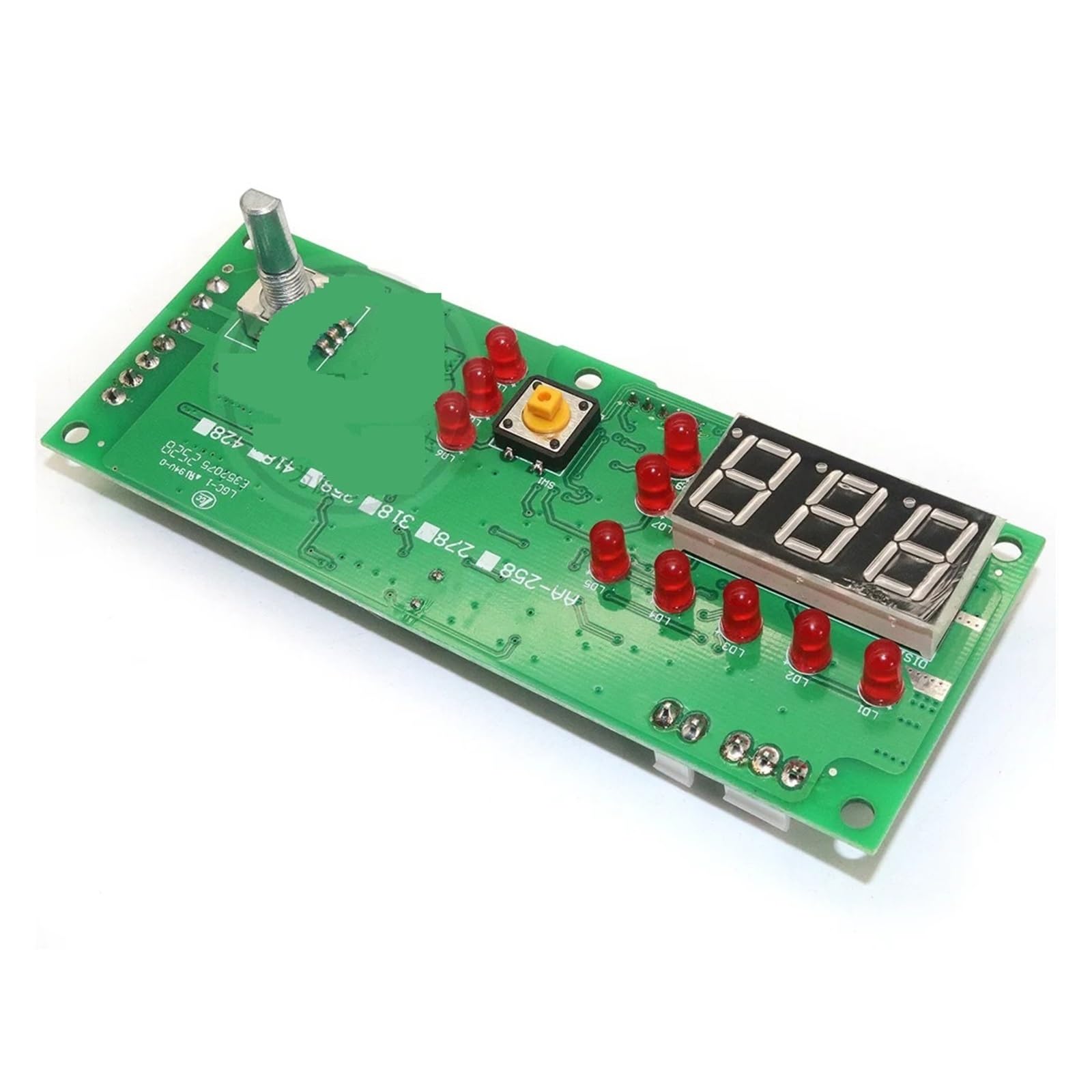
Figure 1: Front view of the TJGOPKUJ ZX7-315 Dual Power Supply Control Board. This image displays the compact design of the circuit board with various electronic components, connectors, and heat sinks visible, indicating its role as a central control unit for an inverter welder.
No official product videos from the seller were found to be relevant for embedding in this manual.
4. Setup and Installation
Installation of the ZX7-315 control board requires careful attention to detail and electrical safety. It is intended for integration into an existing inverter welder chassis.
- Power Disconnection: Before beginning, ensure the main power supply to the welding machine is completely disconnected and verified with a voltmeter.
- Access Chassis: Open the welding machine chassis to access the existing control board or the designated mounting area.
- Mounting: Securely mount the ZX7-315 control board using appropriate fasteners. Ensure it is stable and not subject to vibration.
- Wiring Connections:
- Connect the main power input cables to the designated terminals on the board, observing correct polarity (e.g., AC input, DC bus connections).
- Connect control signals (e.g., current feedback, voltage feedback, fan control, display interface) to their respective pins. Refer to the specific wiring diagram of your welding machine for precise connections.
- Ensure all connections are tight and secure to prevent loose contacts, which can cause arcing or intermittent operation.
- Inspection: Double-check all wiring for correctness, ensuring no wires are pinched or exposed.
- Close Chassis: Carefully close the welding machine chassis, ensuring no wires are caught.
- Initial Power-Up: Connect the welding machine to a suitable power source. Observe for any unusual sounds, smells, or smoke. If any anomalies occur, immediately disconnect power and re-inspect the installation.
5. Operating Instructions
The ZX7-315 control board functions as the brain of your inverter welder. Its operation is integrated into the overall welding machine system. This section outlines general operational principles related to the control board's function.
- Power On/Off: The board powers on and off with the main switch of the welding machine.
- Parameter Control: Welding parameters (e.g., current, voltage, arc force) are typically adjusted via the welding machine's front panel controls. The control board processes these inputs and regulates the power output accordingly.
- IGBT Management: The single tube IGBTs are controlled by the board to switch power efficiently, creating the high-frequency output required for inverter welding.
- Feedback and Protection: The board continuously monitors output parameters and internal temperatures. It incorporates protection circuits to safeguard against overcurrent, overvoltage, and overheating, shutting down the system if unsafe conditions are detected.
- Cooling System: The board manages the cooling fan operation to maintain optimal operating temperatures for the IGBTs and other components.
For detailed instructions on operating your specific welding machine, refer to the manual provided with the complete welding unit.
6. Maintenance
Regular maintenance ensures the longevity and reliable performance of your ZX7-315 control board.
- Dust Removal: Periodically, with the power disconnected, open the welding machine chassis and use compressed air to gently remove dust and debris from the control board and heat sinks. Accumulation of dust can impair cooling and lead to overheating.
- Visual Inspection: Inspect the board for any signs of damage, such as burnt components, loose connections, or swollen capacitors. Address any issues promptly.
- Environmental Conditions: Operate and store the welding machine in a clean, dry environment, free from excessive humidity, corrosive fumes, and extreme temperatures.
- Connection Integrity: Ensure all electrical connections remain tight and free from corrosion.
7. Troubleshooting
If you encounter issues with your inverter welder, the control board may be a factor. Here are some common troubleshooting steps:
| Problem | Possible Cause | Solution |
|---|---|---|
| Welder does not power on. | No power to the board; faulty power supply connection; damaged board. | Check main power input to the welder. Verify all power connections to the control board. Inspect for visible damage. |
| No welding output. | Incorrect control signal; IGBT failure; protection circuit activated. | Ensure welding parameters are set correctly. Check for error codes on the welder's display. Consult a professional for IGBT diagnosis. |
| Overheating. | Blocked airflow; faulty fan; excessive load; damaged heat sink. | Clean dust from the board and fan. Ensure proper ventilation. Reduce welding duty cycle if continuously overheating. |
| Erratic welding performance. | Loose connections; component degradation; interference. | Inspect all signal and power connections for tightness. Ensure proper grounding. |
For complex issues or if troubleshooting steps do not resolve the problem, it is recommended to seek assistance from a qualified technician or the manufacturer's support.
8. Specifications
| Feature | Detail |
|---|---|
| Model | ZX7-315 (Configuration 400) |
| Type | Dual Power Supply Control Board for Inverter Welder |
| Technology | Single Tube IGBT |
| Brand | TJGOPKUJ |
| Item Weight | 3.49 ounces (99 Grams) |
| Package Dimensions | 1.18 x 0.79 x 0.39 inches |
| Power Plug Type | No Plug (Component for integration) |
| ASIN | B0DMW41HLV |
| Date First Available | November 13, 2024 |
9. Warranty and Support
This TJGOPKUJ product is covered by a manufacturer's warranty against defects in materials and workmanship. The specific terms and duration of the warranty may vary. Please retain your proof of purchase for warranty claims.
For technical support, warranty service, or inquiries regarding the ZX7-315 control board, please contact your retailer or the manufacturer directly. Contact information is typically available on the product packaging or the manufacturer's official website.
Note: Damage resulting from improper installation, unauthorized modification, misuse, or failure to follow the instructions in this manual is not covered under warranty.