1. Product Overview
The ciyeu XY7025 is a high-performance CNC DC step-down power supply module designed for applications requiring constant voltage, constant current, and constant power output. It features a wide input voltage range, precise output control, and multiple communication options, including serial TTL and onboard 485 communication with Modbus protocol support. This module also supports MPPT solar charging and firmware upgrades.
- CNC DC step-down power supply with constant voltage, constant current, and constant power capabilities.
- Supports MPPT solar charging.
- Features dual serial ports: serial TTL and onboard 485 communication.
- Standard Modbus protocol support for serial communication.
- Firmware upgradeable.
2. Key Features and Components
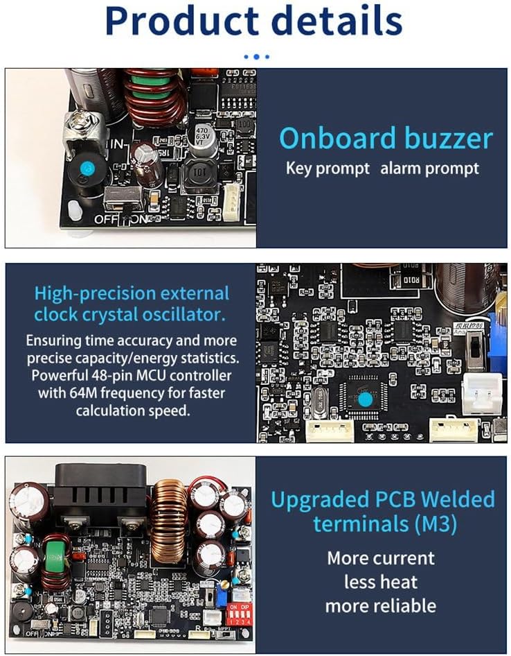
Image Description: This image displays the internal components of the XY7025 power supply. Key features highlighted include an onboard buzzer for key and alarm prompts, a high-precision external clock crystal oscillator for accurate time and energy statistics, and upgraded M3 PCB welded terminals designed for higher current and reduced heat, enhancing reliability.

Image Description: A detailed view of the XY7025 power supply board, illustrating various components and connection points. Labels indicate the input common-mode inductors, high-power magnetic ring inductors, output 2-stage filtering, IN+/IN- terminals, OUT+/OUT- terminals, hard ON/OFF power switch, serial TTL communication, 485 communication, 10k NTC 3950B external temperature sensor interface, and the MPPT hardware switch with an indicator light.
- Onboard Buzzer: Provides audible feedback for key presses and alarm conditions.
- High-Precision External Clock Crystal Oscillator: Ensures accurate time and energy statistics with a powerful 48-pin MCU controller operating at 64MHz for fast calculations.
- Upgraded PCB Welded Terminals (M3): Designed for higher current handling, reduced heat generation, and improved reliability.
- Input Common-Mode Inductors: Significantly reduce input power ripple for a low ripple output.
- High-Power, High-Temperature-Resistant Inductors: Employ iron-silicon-aluminum magnetic ring inductors for robust performance.
- Output 2-Stage Filtering: Ensures clean and stable output power.
- 10k NTC 3950B External Temperature Sensor Interface: Allows for external temperature monitoring.
- MPPT Hardware Switch: Dedicated switch for activating the Maximum Power Point Tracking function, with an indicator light.
3. Setup and Connections
3.1 Safety Precautions
- The input cannot be connected to AC power, nor can it be connected to 220V mains power.
- The maximum input voltage must not exceed 90V. It is recommended to operate within 85V.
- Ensure positive and negative input terminals are connected correctly; reverse connection can damage the device.
- The output has no reverse current protection. When connecting to a battery, ensure the power supply's output voltage is always higher than the battery voltage. Alternatively, a diode can be connected in series with the positive output terminal to allow one-way conduction, preventing reverse current from the battery to the power supply.
- When connecting to the output terminal, pay attention not to connect the positive and negative terminals reversely.
- This product is a DC buck power supply. The maximum output wattage is equal to input voltage * 0.945.
3.2 Wiring Instructions
Refer to the diagram below for proper connection of input power, output load, and communication interfaces.
Image Description: This diagram illustrates the various connection points on the XY7025 module. It shows the IN+ and IN- terminals for power input, OUT+ and OUT- terminals for power output, the hard ON/OFF power switch, serial TTL communication pins, 485 communication pins, the external temperature sensor interface, and the MPPT hardware switch.
- Input Power: Connect your DC input source (12-85V) to the IN+ and IN- terminals. Observe polarity.
- Output Load: Connect your load to the OUT+ and OUT- terminals. Observe polarity.
- Power Switch: Use the hard ON/OFF switch to control the power to the module.
- Communication:
- Serial TTL: Connect to the designated serial TTL pins for communication.
- 485 Communication: Connect to the 485 communication interface for long-distance communication via 485 bus control.
- External Temperature Sensor: Connect a 10k NTC 3950B temperature sensor to the dedicated interface if external temperature monitoring is required.
3.3 Bare Board Configuration (DIP Switches)
The bare board can be used independently, supporting MPPT and analog 0-10V control. It also supports serial communication and onboard 485 communication simultaneously. The output voltage is adjustable from 0-70V, and the output current is adjustable from 0-25A.

Image Description: This image focuses on the XY7025 bare board, emphasizing its independent operation. It clearly states the output voltage range of 0-70V and output current range of 0-25A. The presence of independent dual serial ports (TTL level and onboard 485 communication) is highlighted. A crucial note reminds users that switches, potentiometers, and dial switches are not welded by default when purchasing a bare device, unless a screen meter set is included.
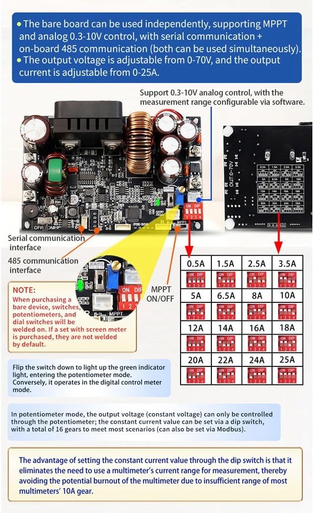
Image Description: This image details the bare board configuration. It highlights the MPPT ON/OFF dip switch, 485 communication interface, and a set of dip switches for setting the constant current value. A potentiometer for voltage adjustment is also visible. A note clarifies that switches, potentiometers, and dial switches are not welded by default when purchasing a bare device without a screen meter.
- MPPT ON/OFF: Use the dedicated dip switch to enable or disable the MPPT function.
- Constant Current Setting (DIP Switches): The constant current value can be set via a series of dip switches, offering 16 gears to meet various scenarios. This can also be set via Modbus. The advantage of setting the constant current value through the dip switch is that it eliminates the need for a multimeter's current range for measurement, avoiding potential burnout of multimeters with insufficient 10A gear.
- Potentiometer Mode: In potentiometer mode, the output voltage (constant voltage) can only be controlled through the potentiometer.
- Note: When purchasing a bare device, switches, potentiometers, and dial switches may not be welded on by default. If a set with a screen meter is purchased, these components are typically pre-welded.
4. Operation
4.1 Basic Operation
- Ensure all connections are secure and correct according to the Setup section.
- Turn on the power supply using the hard ON/OFF switch.
- Adjust the desired output voltage and current using the control interface (if a screen meter is connected) or the potentiometer/DIP switches for bare board operation.
- Monitor the output parameters to ensure stable operation.
4.2 MPPT Solar Charging
The XY7025 supports MPPT (Maximum Power Point Tracking) for solar charging applications. Activate this function using the dedicated MPPT hardware switch. An indicator light will illuminate when MPPT is active.
4.3 Communication Control
The module offers robust communication capabilities for remote control and monitoring.

Image Description: This image demonstrates the 485 bus control capability, allowing multiple XY7025 modules to be connected and controlled remotely. It highlights the independent dual serial ports (TTL level communication and onboard 485 communication) which can be used simultaneously for multi-machine control via PC software.
- Serial TTL: For direct serial communication with microcontrollers or other devices.
- Onboard 485 Communication: Enables remote multi-machine control via a 485 bus. This is particularly useful for low-cost solutions and integration with PC software.
- Modbus Protocol: The module supports the standard Modbus protocol for serial communication, facilitating integration into existing control systems.
4.4 Data Storage
The XY7025 module supports storage of up to 10 data groups, allowing users to save and recall frequently used voltage and current settings.
5. Maintenance
- Keep the module clean and free from dust and debris to ensure proper heat dissipation.
- Ensure adequate ventilation around the module during operation to prevent overheating.
- Regularly check all connections for tightness and signs of wear or corrosion.
- Avoid exposing the module to moisture or extreme temperatures.
6. Troubleshooting and Protection Mechanisms
The XY7025 incorporates several protection mechanisms to ensure safe operation. If an issue occurs, check the following:
| Protection Type | Description | Default / Adjustable Range |
|---|---|---|
| Under-Voltage Protection (LVP) | Shuts down output if input voltage drops below a set threshold. | Adjustable 10-95V, Default 10V |
| Over-Voltage Protection (OVP) | Shuts down output if output voltage exceeds a set threshold. | Adjustable 0-72V, Default 72V |
| Over-Current Protection (OCP) | Shuts down output if output current exceeds a set threshold. | Adjustable 0-27A, Default 27A |
| Over-Power Protection (OPP) | Shuts down output if output power exceeds a set threshold. | Adjustable 0-2000W, Default 1800W |
| Over-Temperature Protection (OTP) | Shuts down output if internal temperature exceeds a set threshold. | Adjustable 0-110°C, Default 95°C |
| Over-Time Protection (OHP) | Shuts down output after a set operating duration. | 1 minute - 99 hours 59 minutes, Default OFF |
| Over-Capacity Protection (OAP) | Shuts down output after a set total output capacity. | 0-9999Ah, Default OFF |
| Over-Energy Protection (OPH) | Shuts down output after a set total output energy. | 0-4200KWh, Default OFF |
If any of these protections are triggered, the power supply will cease operation. Identify and resolve the underlying cause (e.g., excessive load, incorrect input voltage, high ambient temperature) before restarting the module.
7. Technical Specifications
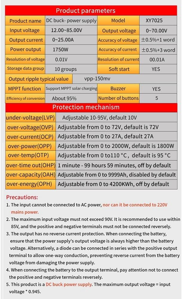
Image Description: This image presents a comprehensive table of technical specifications for the XY7025 module. It lists parameters such as input voltage, output voltage, output current, power output, resolution, accuracy, conversion efficiency, MPPT function support, storage groups, and details for all protection mechanisms (LVP, OVP, OCP, OPP, OTP, OHP, OAP, OPH).
| Parameter | Value |
|---|---|
| Product Name | DC Buck Power Supply |
| Model | XY7025 |
| Input Voltage | 12.00-85.00V |
| Output Voltage | 0.0-70.00V |
| Output Current | 0-25.00A |
| Power Output | 1750W |
| Voltage Resolution | 0.01V |
| Current Resolution | 0.01A |
| Voltage Accuracy | ±0.5%+1 word |
| Current Accuracy | ±0.5%+3 word |
| Efficiency of Conversion | About 95% |
| MPPT Function | Support MPPT solar charging |
| Storage Data Group | 10 groups |
| Soft Start | YES |
| Output Ripple Typical Value | Vpp-150mV |
| Buzzer | YES |
| Number of Buttons | 5 |
| Product Dimensions | 14.2 x 10.7 x 4.6 cm |
| Item Weight | 230 g |
| Material | PCB + Electronic Components |