1. Introduction
This manual provides essential information for the safe and effective operation of your Hantek DPO7504U Digital Oscilloscope. Please read this manual thoroughly before using the device to ensure proper functionality and to prevent damage.

Figure 1.1: Hantek DPO7504U Digital Oscilloscope and its complete set of accessories.
2. Safety Information
Always observe the following safety precautions to avoid injury and prevent damage to the instrument:
- Power Source: Connect the instrument only to the power source specified in this manual or on the product label.
- Grounding: Ensure the instrument is properly grounded to prevent electric shock.
- Probes: Use only probes supplied or recommended by Hantek. Ensure probes are rated for the voltage being measured.
- Environment: Operate the oscilloscope in a dry, well-ventilated area. Avoid extreme temperatures, humidity, and dusty environments.
- Maintenance: Refer all servicing to qualified service personnel. Do not attempt to repair the unit yourself.
3. Setup
3.1 Unpacking and Inspection
Upon receiving your Hantek DPO7504U, carefully unpack all components and inspect them for any signs of damage during transit. If any items are damaged or missing, contact your supplier immediately.
The package should contain:
- Hantek DPO7504U Digital Oscilloscope Unit
- Power Cable
- Oscilloscope Probes (quantity as specified)
- USB Cable
- User Manual (this document)
- Probe Accessories (e.g., color rings, ground clips)
3.2 Connecting Power
- Ensure the oscilloscope's power switch is in the OFF position.
- Connect the provided power cable to the power input port on the rear panel of the oscilloscope.
- Plug the other end of the power cable into a grounded AC power outlet.
3.3 Connecting Probes
To connect an oscilloscope probe:
- Align the BNC connector of the probe with one of the input channels (CH1, CH2, CH3, CH4) on the front panel.
- Push the connector in and twist it clockwise until it locks into place.
- Attach the probe's ground clip to the circuit's ground point.
- Adjust the probe compensation if necessary (refer to the Operating section).

Figure 3.1: Oscilloscope probe BNC connector.
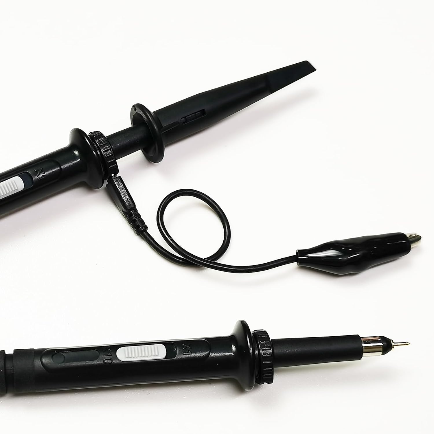
Figure 3.2: Oscilloscope probe tip with hook accessory.
4. Operating Instructions
4.1 Powering On and Initial Display
Press the power button on the front panel to turn on the oscilloscope. The device will perform a self-test and then display the main waveform interface on its 10.1-inch multi-touch capacitive screen.

Figure 4.1: The 10.1-inch multi-touch capacitive screen provides a clear display for waveform analysis.
4.2 Basic Controls
The DPO7504U features a user-friendly interface with dedicated controls for vertical, horizontal, and trigger settings.
- Vertical Controls: Adjust voltage per division (V/div) and vertical position for each channel.
- Horizontal Controls: Adjust time per division (s/div) and horizontal position to control the time base.
- Trigger Controls: Set the trigger level, mode, and source to stabilize waveforms.

Figure 4.2: Overview of the Hantek DPO7504U oscilloscope's display and controls.
4.3 Waveform Acquisition and Display
The oscilloscope offers a 500MHz bandwidth and a 2GSa/s sampling rate across its 4 channels, allowing for detailed signal analysis. The 2Gpts memory depth ensures that even long signal captures retain high resolution.

Figure 4.3: The 2G memory depth allows for comprehensive waveform capture without losing fine details.
The 256-level waveform gray scale and color temperature display enhance the visualization of signal activity, making it easier to identify infrequent events or signal anomalies.
4.4 Waveform Generator
The DPO7504U includes a built-in 25MHz waveform generator capable of producing standard and arbitrary waveforms. To use the waveform generator:
- Access the waveform generator menu from the main interface.
- Select the desired waveform type (e.g., sine, square, pulse, arbitrary).
- Adjust parameters such as frequency, amplitude, and offset.
- Connect the output of the waveform generator (G1 Out on the rear panel) to your circuit.

Figure 4.4: The integrated 25MHz arbitrary waveform generator supports various signal outputs.
4.5 Measurement Functions
The oscilloscope provides 51 types of automatic measurements, simplifying signal analysis. It also features a 5-bit digital voltmeter and a 6-bit hardware frequency meter.

Figure 4.5: Automatic measurement functions provide real-time statistics for efficient testing.
4.6 Advanced Features
- Waveform Capture Rate: Up to 500,000 wfms/s for capturing transient events.
- Area Trigger: Allows users to define a specific region on the screen to trigger on, simplifying the isolation of complex waveform events.
- Waveform Recording: Provides real-time, uninterrupted recording of waveform changes, with time markers for easy playback and fault identification.

Figure 4.6: The Area Trigger function helps isolate specific waveform events by defining a trigger region.

Figure 4.7: Waveform recording allows for detailed analysis of signal changes over time.
5. Maintenance
5.1 Cleaning the Instrument
To maintain the performance and appearance of your oscilloscope:
- Disconnect the power cord before cleaning.
- Use a soft, damp cloth with a mild detergent to clean the exterior surfaces. Avoid abrasive cleaners or solvents.
- For the screen, use a soft, lint-free cloth specifically designed for electronic displays.
- Ensure no liquid enters the instrument.
5.2 Probe Care
Oscilloscope probes are delicate instruments. Handle them with care:
- Avoid bending or stressing the probe cable excessively.
- Keep probe tips clean and free from debris.
- Store probes properly to prevent damage to the tips and connectors.
5.3 Storage
When not in use, store the oscilloscope in a clean, dry environment, away from direct sunlight, extreme temperatures, and vibrations.
6. Troubleshooting
This section provides solutions to common issues you might encounter. For problems not listed here, contact Hantek support.
| Problem | Possible Cause | Solution |
|---|---|---|
| No power when turned on | Power cable not connected; Power outlet faulty; Instrument fuse blown | Check power cable connection; Test power outlet; Contact service for fuse replacement. |
| No waveform displayed | Probe not connected; Input signal too small/large; Trigger settings incorrect; Channel turned off | Connect probe correctly; Adjust V/div; Adjust trigger level/mode; Ensure channel is enabled. |
| Unstable waveform | Incorrect trigger settings; Noisy signal; Probe compensation incorrect | Adjust trigger level/mode; Use averaging mode; Perform probe compensation. |
| Touch screen unresponsive | Temporary software glitch; Screen calibration issue | Restart the instrument; Refer to advanced settings for screen calibration if available. |
7. Specifications
The following table outlines the key technical specifications for the Hantek DPO7504U Digital Oscilloscope:
| Parameter | Specification |
|---|---|
| Model | DPO7504U |
| Channels | 4 |
| Bandwidth | 500 MHz |
| Real-time Sampling Rate | 2 GSa/s |
| Memory Depth | 2 Gpts |
| Waveform Capture Rate | Up to 500,000 wfms/s |
| Display | 10.1-inch Multi-touch Capacitive Screen |
| Waveform Generator | 25 MHz (Arbitrary Wave Output) |
| Automatic Measurements | 51 types |
| Digital Voltmeter | 5-bit |
| Hardware Frequency Meter | 6-bit |
| Manufacturer | Hantek |

Figure 7.1: The Hantek DPO7504U functions as both a 4-channel oscilloscope and a 1-channel waveform generator.
8. Warranty and Support
8.1 Warranty Information
Warranty terms and conditions for the Hantek DPO7504U Digital Oscilloscope are typically provided at the time of purchase or can be found on the official Hantek website. Please retain your proof of purchase for warranty claims.
8.2 Technical Support
For technical assistance, troubleshooting beyond this manual, or service inquiries, please contact Hantek customer support. You can find contact information and additional resources on the official Hantek website or their Amazon store page: Hantek Amazon Store.