YILTION OPM-NF-916
YILTION NF-916 Network Cable Tester User Manual
Model: OPM-NF-916 | Brand: YILTION
1. Introduction
The YILTION NF-916 is a versatile 4-in-1 testing device designed for network and fiber optic applications. It integrates an Optical Power Meter (OPM), Visual Fault Locator (VFL), RJ45/RJ11/CAT5/CAT6 continuity tester, and wire tracing capabilities. This manual provides detailed instructions for the proper use, maintenance, and troubleshooting of your NF-916 device.
2. Safety Information
- Always handle the device with care to prevent damage.
- Do not expose the device to extreme temperatures, humidity, or corrosive environments.
- Avoid direct eye exposure to the VFL laser output. The laser is a Class IIIA laser product.
- Ensure proper connection of cables and fibers before performing tests.
- Keep the device away from children.
- Use only the specified charging cable and power adapter.
3. Product Overview
The NF-916 combines multiple essential functions for network and fiber optic professionals into a compact and user-friendly device.

Figure 3.1: NF-916 Device Components and Interfaces. This diagram labels the OPM interface, VFL interface, screen, Type-C charging port, RJ45 interface, line sequence indicator, and various control buttons including VFL/Lamp, REF, AUTO, CONT, Unit/QC, and WAVE. It also shows the detachable remote unit for RJ45 testing.
Key Features:
- Optical Power Meter (OPM): Supports 850/980/1310/1490/1550/1625nm wavelengths with a test range of -70dBm to +6dBm. Features automatic identification of optical power frequency and a reference function for accurate measurements.
- Visual Fault Locator (VFL): 10mW red laser with three modes: constant light, slow flash, and fast flash, for comprehensive fiber diagnostics. Supports FC/SC/ST universal interfaces.
- RJ45/RJ11/CAT5/CAT6 Continuity Test: Fast and slow cable continuity testing for modules and RJ45 network connections. Includes automatic verification of single-ended RJ45 plug crimp tests.
- Wire Tracer: Aids in identifying and tracing network cables.
- High Brightness LED Flashlight: Integrated for working in dark environments.
- Compact and Portable Design: Easy to carry and operate.
4. Setup
4.1 Unpacking and Initial Inspection
Upon receiving your NF-916, carefully unpack all components and inspect for any signs of damage. The package should include the main unit (transmitter), a remote unit, a USB Type-C cable, and this user manual.

Figure 4.1: NF-916 Product and Packaging. The image displays the NF-916 device alongside its retail box, highlighting its multi-functionality as an Optical Fiber Tester, Network Cable Tester, RJ45 Cable Tester, CAT5/CAT6/CAT3 tester, and VFL.
4.2 Charging the Device
Before first use, fully charge the NF-916 using the provided USB Type-C cable. Connect the cable to the Type-C charging port on the side of the device and to a standard USB power source (e.g., computer USB port, wall adapter).
5. Operating Instructions
5.1 Optical Power Meter (OPM) Function
The OPM function measures the optical power of fiber optic signals.
- Power on the NF-916.
- Connect the fiber optic cable to the OPM interface (labeled OPM) on the top of the device. The NF-916 supports FC/SC/ST universal interfaces.
- Press the WAVE button to cycle through the supported wavelengths (850nm, 980nm, 1310nm, 1490nm, 1550nm, 1625nm) to match your testing requirements.
- The measured optical power in dBm will be displayed on the screen.
- Use the REF button to set a reference value for relative power measurements.

Figure 5.1: Optical Power Measurement. This image shows the NF-916 display during an OPM test, indicating the wavelength (e.g., 1310nm) and the measured power level. It also lists the six supported wavelengths: 850nm, 980nm, 1310nm, 1490nm, 1550nm, and 1625nm.
5.2 Visual Fault Locator (VFL) Function
The VFL function uses a red laser to identify breaks, bends, or poor connections in fiber optic cables.
- Power on the NF-916.
- Connect the fiber optic cable to the VFL interface (labeled VFL) on the top of the device.
- Press the VFL/Lamp button repeatedly to cycle through the VFL modes: Steady On, Slow Flashing, and Fast Flashing.
- Observe the fiber for red light leakage, which indicates a fault.

Figure 5.2: Visual Fault Locator in Use. This image demonstrates the NF-916's VFL function, showing a strong red laser being emitted through an optical fiber, indicating its ability to trace and locate faults.
5.3 RJ45 Network Cable Test (Continuity & QC)
This function tests the continuity and crimping quality of RJ45 network cables (CAT5, CAT6) and RJ11 cables.
- Detach the remote unit from the main NF-916 device by pressing the release button on the back.
- Connect one end of the network cable to the RJ45 port on the main unit and the other end to the RJ45 port on the remote unit.
- The screen on the main unit will display the continuity test results, showing which wires are correctly connected.
- For crimp quality check (QC function), connect a single-ended RJ45 plug to the main unit's RJ45 port. The device will automatically verify the crimping accuracy.

Figure 5.3: RJ45 Network Test Setup. This image illustrates the split design of the NF-916, with the main unit connected to one end of an RJ45 cable and the detachable remote unit connected to the other end, demonstrating its use for network cable testing.
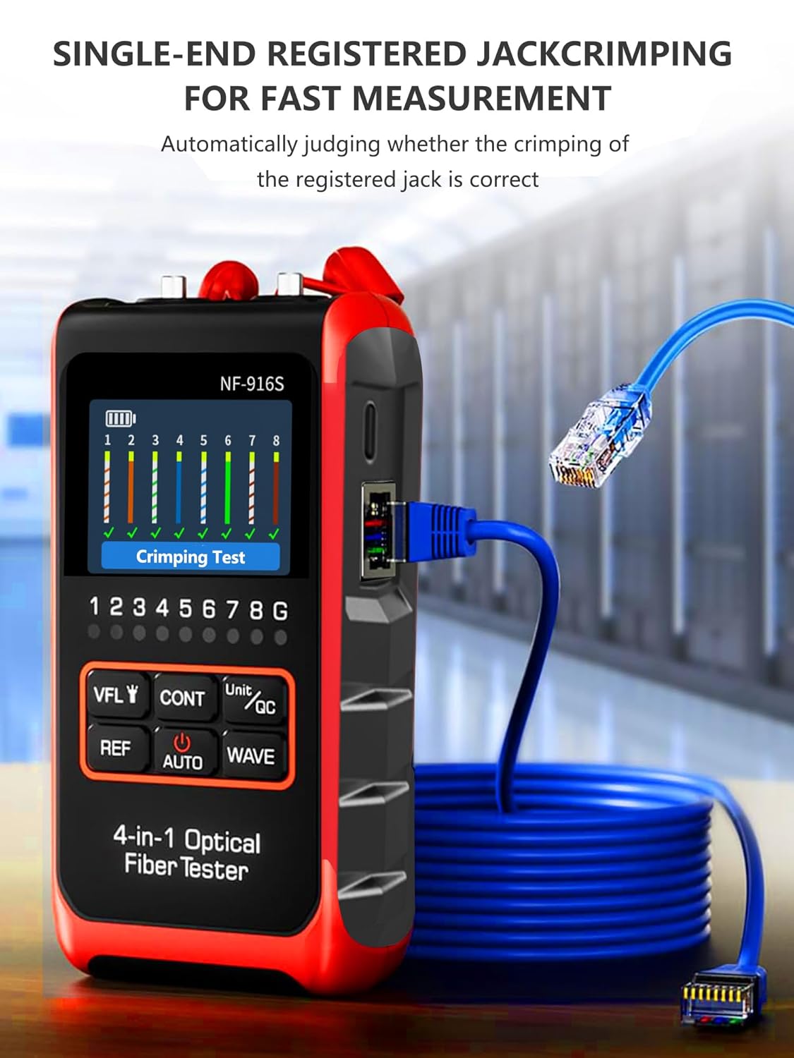
Figure 5.4: Single-Ended RJ45 Crimping Test. The image shows the NF-916 performing a crimping test on a single RJ45 connector, with the display indicating the status of each wire, ensuring correct crimp quality.
5.4 Wire Tracing Function
The wire tracing function helps locate specific cables within a bundle or wall.
- Connect the network cable to the main unit.
- Activate the wire tracing mode (refer to device interface for specific button/menu option, usually integrated with continuity test).
- Use the remote unit or a compatible probe (not included) to trace the cable. The device will emit a signal that can be detected by the probe, helping to identify the correct cable.
5.5 Integrated LED Flashlight
To activate the high-brightness LED flashlight, press the VFL/Lamp button briefly when the VFL is off. Press again to turn off.
Video 5.1: Demonstration of NF-916 Features. This video provides a comprehensive overview of the NF-916's capabilities, including its optical power meter function, visual fault locator modes (steady, slow flash, fast flash), and RJ45 network testing with the detachable remote unit. It also highlights the integrated LED flashlight for use in dark environments.
6. Maintenance
- Cleaning: Use a soft, dry cloth to clean the device. Do not use abrasive cleaners or solvents. For optical interfaces, use specialized fiber optic cleaning tools.
- Storage: Store the device in a cool, dry place, away from direct sunlight and extreme temperatures. Use the provided carrying case for protection.
- Battery Care: To prolong battery life, avoid fully discharging the battery frequently. If storing for extended periods, charge the battery to about 50% every few months.
- Interface Protection: Always keep the protective caps on the OPM and VFL interfaces when not in use to prevent dust and damage.
7. Troubleshooting
| Problem | Possible Cause | Solution |
|---|---|---|
| Device does not power on. | Low battery; device malfunction. | Charge the device fully. If problem persists, contact support. |
| Inaccurate OPM readings. | Dirty optical interface; incorrect wavelength setting; damaged fiber. | Clean the OPM interface. Verify wavelength setting. Check fiber for damage. |
| VFL laser is dim or not visible. | Dirty VFL interface; low battery; damaged laser diode. | Clean the VFL interface. Charge the device. Contact support if laser is still dim. |
| RJ45 continuity test fails. | Faulty cable; incorrect connection; remote unit not attached/powered. | Ensure cable is not damaged. Verify both ends are securely connected. Ensure remote unit is properly attached or functioning. |
8. Specifications
- Model Number: OPM-NF-916
- Package Dimensions: 8.19 x 4.8 x 2.05 inches
- Item Weight: 8.47 ounces
- Manufacturer: YILTION
- Color: Red
- Optical Power Meter Wavelengths: 850/980/1310/1490/1550/1625nm (6 wavelengths)
- Optical Power Meter Test Range: -70dBm ~ +6dBm
- VFL Output Power: 10mW
- VFL Modes: Constant light, Slow flash, Fast flash
- Fiber Interface: FC/SC/ST Universal Interface
- Network Cable Test: RJ45/RJ11/CAT5/CAT6 Continuity Test, Single-Ended RJ45 Crimp Test
- Power Source: Internal rechargeable battery (3.7V Li-ion, 700mAh)
- Charging Port: USB Type-C
9. Warranty and Support
For warranty information and technical support, please refer to the documentation provided with your purchase or contact YILTION customer service directly. Keep your purchase receipt as proof of purchase for warranty claims.
Ask a question about this manual
Ask about setup, troubleshooting, compatibility, parts, safety, or missing instructions. Manuals+ will review the question and use this page’s manual context to help answer it.