1. Product Overview
This document provides essential information for the installation, operation, and maintenance of the Replacement Cast Iron Blade Deck Spindle. This high-quality replacement part is designed to restore optimal performance to your zero-turn mower's cutting deck.
Key features include:
- Premium Durability: Constructed with robust materials for longevity and reliable performance.
- Precise Fit & Simple Installation: Engineered for a perfect fit, allowing for quick and hassle-free installation.
- Enhanced Performance: Designed to meet or surpass OEM specifications for peak efficiency.
- Affordable Maintenance Solution: A cost-effective solution for maintaining your machinery.
- Wide Compatibility: Compatible with a range of Simplicity models.
2. Compatibility
This replacement spindle (Part Number: 5100993SM) is compatible with various Simplicity models, particularly those with a 61-inch mower deck. Refer to the list below to confirm compatibility with your specific model:
- 5900509 Massey Ferguson 3000 52"
- 5901532 72 Inch Mower Deck 4900/72 Ansi-exp
- 5901336 72"
- 5901460 61 Inch Mower Deck
- 5900530 Massey Ferguson 3000 52"
- 5901531 61 Inch Mower Deck 4900/61 Ansi-exp
- 5900527 Cobalt 61" Deck
- 5900526 Cobalt 26Hp For Kawasaki
- 5900819 Cobalt 61" Deck
- 2690479 Cobalt 27Hp Kohler
- 5900525 Cobalt 30Hp Briggs Stratton
- 5901305 Cobalt 61 Inch Zero-turn Mower 26hp Briggs And Stratton
- 5901492 Cobalt 61 Inch Zero-turn Mower 28hp Briggs And Stratton
- 5901306 Cobalt 61 Inch Zero-turn Mower 32hp Briggs And Stratton
- 5901339 Cobalt 61 Inch Zero-turn Mower 32hp Briggs And Stratton
- 5901338 Cobalt 61 Inch Zero-turn Mower 26hp Briggs And Stratton
- 5900763 Cobalt 30Hp Briggs Stratton
- 5900597 3900 28Hp Briggs Stratton
- 5900531 3900 30Hp Briggs Stratton
- 5901240 3900 28Hp Briggs Stratton
3. Specifications
| Attribute | Detail |
|---|---|
| Part Number | 5100993SM |
| Deck Size Compatibility | 61 inches |
| Item Height | 197.2 mm |
| Item Width | 197.2 mm |
| Item Length | 180 mm |
| Item Weight | 8.5 pounds |
| Mounting Hole Distance | 173 mm |
| Manufacturer | Generic |
| Manufacturer Part Number | UERWQF25032 |
4. Setup and Installation
Proper installation is crucial for the performance and longevity of your new spindle. Always refer to your mower's original service manual for specific instructions and safety precautions. The following are general guidelines:
- Safety First: Ensure the mower is turned off, spark plug wire is disconnected (for gasoline models), and the deck is safely raised or removed from the mower frame. Wear appropriate personal protective equipment (PPE), including gloves and eye protection.
- Access the Deck: Depending on your mower model, you may need to remove the entire deck or simply raise it to access the spindles.
- Remove Old Spindle: Loosen and remove the bolts securing the old spindle to the deck. Carefully detach the blade from the bottom of the spindle. Note the orientation of any spacers or washers.
- Clean Mounting Area: Thoroughly clean the mounting surface on the deck to ensure a flat, secure fit for the new spindle. Remove any debris, rust, or old gasket material.
- Install New Spindle: Position the new spindle onto the deck, aligning the mounting holes. Apply thread locker to the bolts if recommended by your mower's manual. Securely fasten the spindle with the appropriate bolts, tightening them to the manufacturer's specified torque.
- Attach Blade: Reattach the mower blade to the bottom of the new spindle. Ensure the blade is oriented correctly (cutting edge facing down) and the blade bolt is tightened to the specified torque.
- Final Checks: Verify that the spindle is securely mounted and the blade spins freely without obstruction. Reconnect the spark plug wire and test the mower in a safe, open area.
If you are unsure about any step, consult a qualified service technician.
5. Operating Considerations
The blade deck spindle is a critical component of your mower's cutting system. Once installed, it facilitates the rotation of the mower blades, enabling efficient grass cutting. Proper operation relies on the spindle being securely mounted and the blade balanced and sharp.
After installation, listen for any unusual noises or vibrations during operation. These could indicate an issue with installation or a need for further inspection.
6. Maintenance
Regular maintenance extends the life of your spindle and ensures consistent cutting performance:
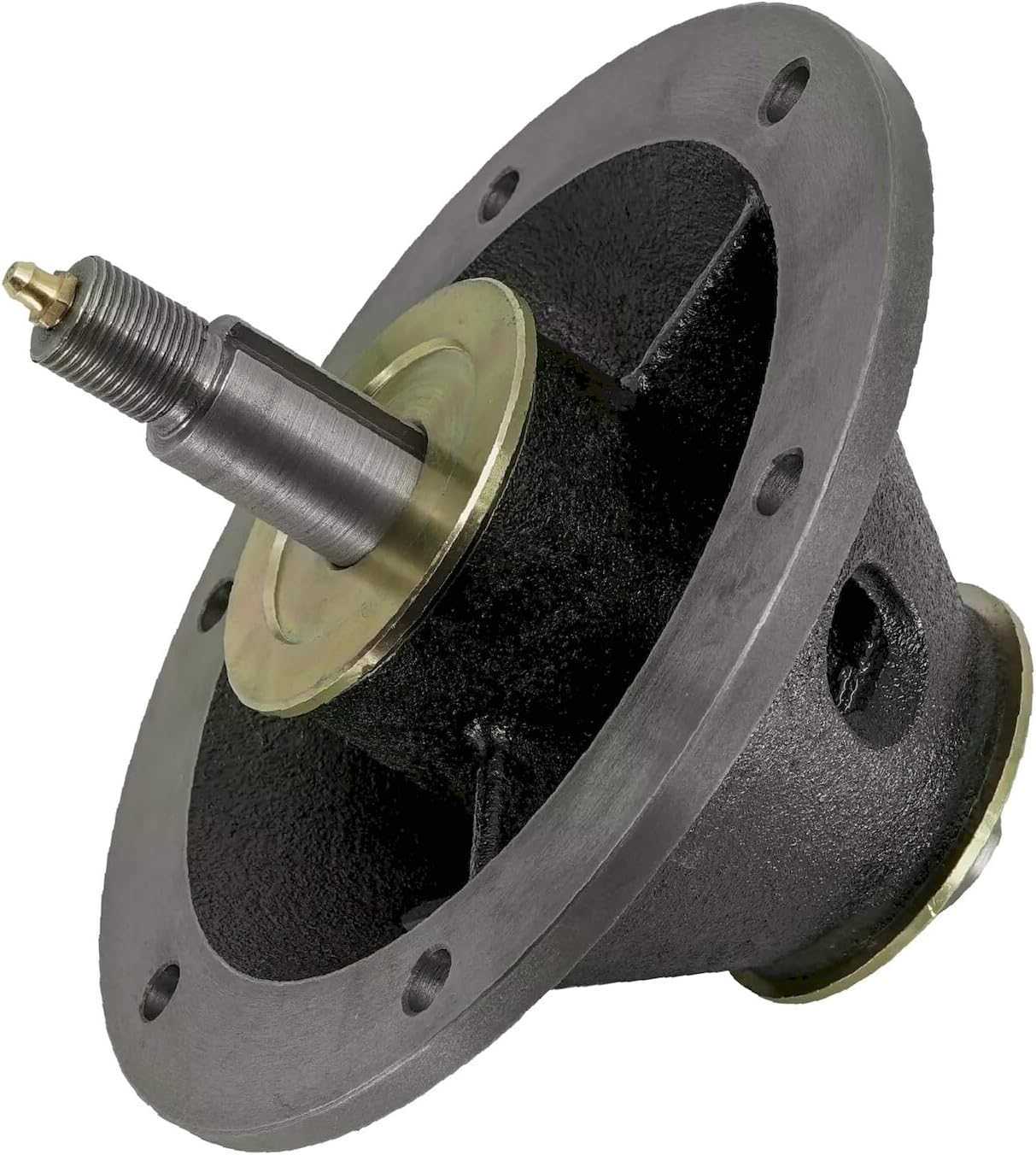
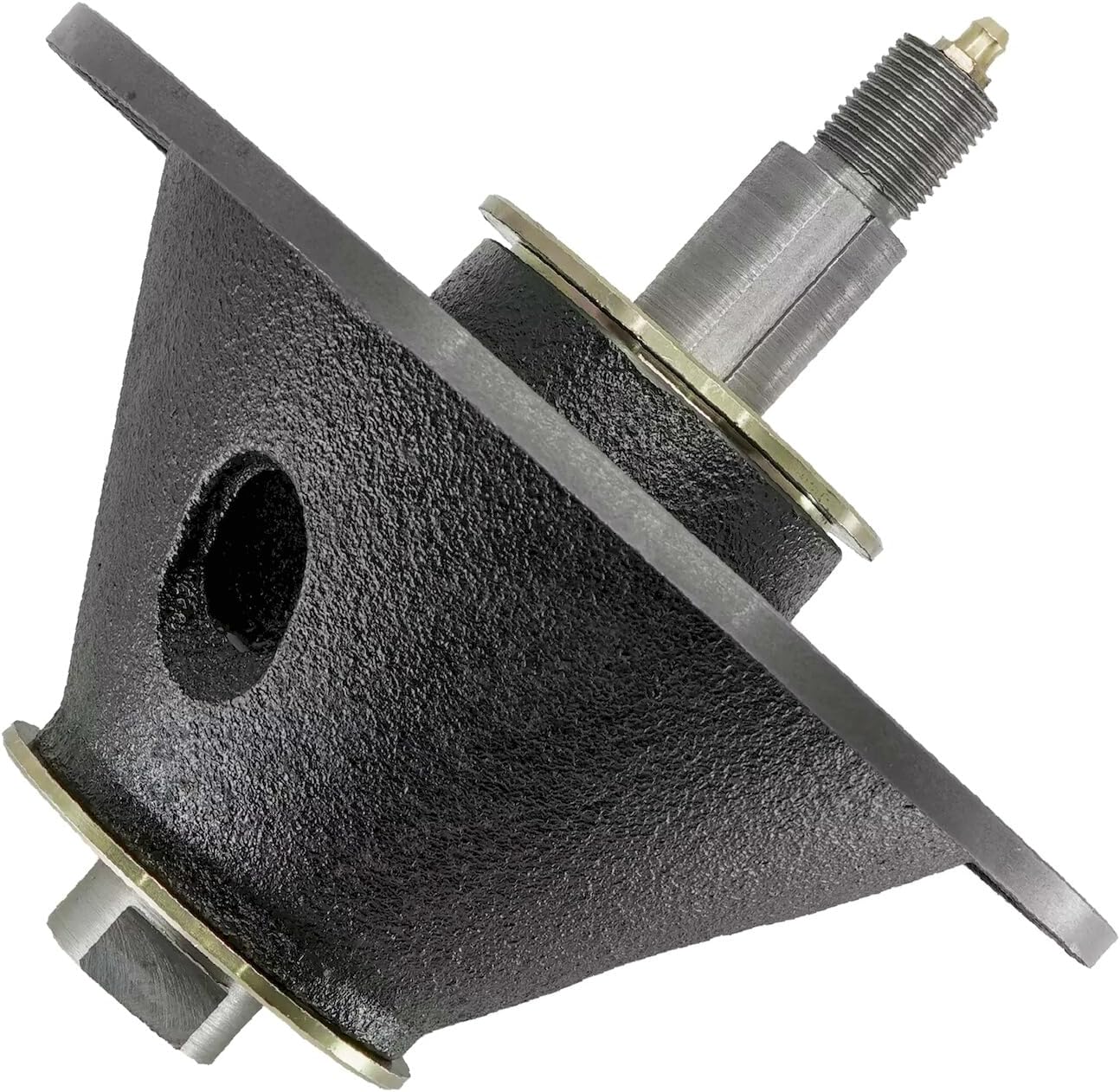
- Lubrication: If your spindle features a grease zerk (as indicated by the presence of a zerk fitting in the product images), lubricate it periodically with appropriate grease as specified in your mower's manual. This typically involves a few pumps of a grease gun until resistance is felt or old grease is purged.
- Inspection: Regularly inspect the spindle for signs of wear, damage, or looseness. Check for excessive play in the shaft, which could indicate worn bearings.
- Blade Condition: Ensure mower blades are sharp and balanced. Unbalanced blades can cause excessive vibration, leading to premature spindle wear.
- Cleaning: Keep the area around the spindle free of grass clippings and debris, which can trap moisture and accelerate corrosion.
- Bolt Torque: Periodically check the torque of the mounting bolts to ensure they remain tight.
7. Troubleshooting
If you experience issues after installing the new spindle, consider the following:
| Symptom | Possible Cause | Solution |
|---|---|---|
| Excessive Vibration | Unbalanced blade, loose mounting bolts, bent shaft (unlikely for new part), debris in deck. | Check blade balance and sharpness. Ensure all mounting bolts are tightened to specification. Clean underside of deck. |
| Unusual Noise (Grinding, Squealing) | Lack of lubrication, worn bearings (unlikely for new part), foreign object. | Apply grease if applicable. Inspect for foreign objects. If noise persists, inspect bearings. |
| Poor Cut Quality | Dull or bent blade, incorrect blade installation, spindle not rotating freely. | Sharpen or replace blade. Verify blade is installed correctly. Check for obstructions preventing spindle rotation. |
| Spindle Overheating | Lack of lubrication, excessive friction, worn bearings. | Lubricate thoroughly. Ensure no binding. If issue persists, professional inspection may be needed. |
If troubleshooting steps do not resolve the issue, contact a qualified service technician or the product supplier for assistance.
8. Product Images


9. Warranty and Support
Specific warranty details for this replacement part are not provided in this manual. Please refer to the original purchase documentation or contact the seller directly for information regarding warranty coverage, returns, and technical support.
For further assistance or inquiries, please reach out to the product supplier or a certified service center for your Simplicity mower.