1. Introduction
This manual provides essential information for the safe and efficient use of the ACLDOYYV Electro-Pneumatic Regulator, ITV2050 Series. This device is designed to precisely control pneumatic pressure based on an electrical input signal. Please read this manual thoroughly before installation, operation, or maintenance to ensure proper function and prevent damage or injury.
2. Safety Information
Adherence to the following safety guidelines is crucial for preventing accidents and ensuring the longevity of the product.
- Always disconnect power and depressurize the pneumatic system before performing any installation, maintenance, or troubleshooting.
- Ensure that the electrical supply voltage matches the specifications of the regulator.
- Install the regulator in a clean, dry environment, free from excessive vibration, corrosive gases, or extreme temperatures.
- Use appropriate personal protective equipment (PPE) when working with pressurized systems.
- Only qualified personnel should perform installation and maintenance procedures.
- Do not exceed the maximum operating pressure specified for the device.
3. Product Overview
The ACLDOYYV ITV2050 Series Electro-Pneumatic Regulator converts an electrical signal into a proportional pneumatic output pressure. It features a digital display for easy monitoring and precise control.
3.1. Components and Features
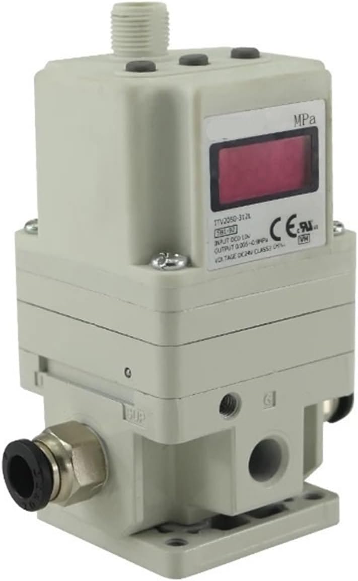
Figure 1: Angled view of the ACLDOYYV ITV2050 Series Electro-Pneumatic Regulator, showing the digital display, pressure ports, and electrical connection point.

Figure 2: Front view of the regulator, highlighting the digital display which shows the current pressure reading in MPa.

Figure 3: Front view showing the digital display and the quick-connect pneumatic fittings on both sides for air input and output.

Figure 4: Side view of the regulator, illustrating the control buttons for setting parameters and the multi-pin electrical connector for power and signal input.

Figure 5: Bottom view of the regulator, showing the mounting holes for secure installation and additional pneumatic ports.

Figure 6: Close-up view of a threaded pneumatic port, indicated by a blue arrow, for connecting air lines.
4. Setup and Installation
4.1. Mounting
Mount the regulator vertically on a stable surface using appropriate screws through the designated mounting holes. Ensure sufficient space around the unit for ventilation and access to connections.
4.2. Pneumatic Connections
- Connect the main air supply line to the designated input port (typically marked 'P' or 'IN'). Ensure the air supply is filtered and dry.
- Connect the output line to the designated output port (typically marked 'A' or 'OUT').
- If applicable, connect the exhaust port (typically marked 'R' or 'EXH') to an exhaust line or leave open to atmosphere in a safe manner.
- Use appropriate thread sealant for all threaded connections to prevent leaks.
4.3. Electrical Connections
Connect the power supply and control signal wires to the electrical connector according to the wiring diagram provided with your specific model. Ensure correct polarity for DC power. Incorrect wiring can damage the unit.
5. Operation
5.1. Powering On
Once all pneumatic and electrical connections are secure, apply power to the regulator. The digital display will illuminate, showing the current output pressure or a default setting.
5.2. Pressure Adjustment
The output pressure is controlled by an electrical input signal (e.g., 0-10V, 4-20mA). Refer to your system's control documentation for how to generate the appropriate signal. The regulator will adjust the pneumatic output pressure proportionally to this input signal. Fine adjustments can typically be made using the 'UP' and 'DOWN' buttons on the side of the unit, often after unlocking the controls (refer to specific model instructions for button functions).
5.3. Display Information
The digital display typically shows the current output pressure in MPa. Some models may also display input signal values or error codes. Consult the detailed specifications for your model for a complete understanding of display indicators.
6. Maintenance
6.1. Routine Checks
- Periodically inspect all pneumatic connections for leaks.
- Check electrical connections for tightness and signs of wear.
- Ensure the air supply is clean and dry. Replace air filters as necessary in the upstream system.
- Monitor the regulator's performance and output pressure for any deviations from expected values.
6.2. Cleaning
Clean the exterior of the regulator with a soft, damp cloth. Do not use abrasive cleaners or solvents, as these may damage the housing or display. Ensure no moisture enters the electrical components.
7. Troubleshooting
| Issue | Possible Cause | Solution |
|---|---|---|
| No pressure output | No air supply; Regulator not powered; Incorrect electrical signal. | Check air supply pressure; Verify power connection; Check input signal wiring and value. |
| Unstable pressure output | Fluctuating air supply; Leaks in pneumatic lines; Faulty input signal. | Ensure stable air supply; Check all connections for leaks; Verify stability of input signal. |
| Display not working | No power; Damaged display. | Check power connection; Contact support if power is present. |
| Regulator not responding to input signal | Incorrect wiring; Signal outside range; Internal fault. | Verify electrical wiring; Ensure signal is within specified range; Contact support. |
8. Specifications
| Specification | Value |
|---|---|
| Manufacturer | ACLDOYYV |
| Part Number | ACLDOYYV |
| Item Model Number | ACLDOYYV |
| Model | ITV2050-212S |
| Item Weight | 1.76 ounces |
| Package Dimensions | 1.18 x 0.79 x 0.39 inches |
| Size | One Size |
| Color | ITV2050-212S |
| Item Package Quantity | 1 |
| Number Of Pieces | 1 |
| Date First Available | November 9, 2024 |
9. Warranty and Support
For warranty information and technical support, please refer to the documentation provided with your purchase or contact the manufacturer directly. Keep your proof of purchase for any warranty claims.