1. Introduction
The DONGKER XY-6506X is a DC-DC 390W 6A CVCC (Constant Voltage Constant Current) adjustable automatic buck power supply module. This non-isolated converter is designed to convert DC 12V-72V input to a stable DC 0.0V-65V output. It features a large LCD display and supports MPPT (Maximum Power Point Tracking) for solar charging applications. This module can function as a general buck power supply, a battery/solar charger, or an LED constant current driver.
2. Key Features
- Adjustable CVCC Control Output
- MPPT Solar Charging Control
- 390W High Power Capability
- Large LCD Display Screen for clear readings
- Multiple Protection Mechanisms (Input Under-voltage, Output Over-voltage, Output Over-current, Output Over-power, Over-temperature, Timeout, Over-capacity, Over-energy)
- Power-down Memory Function
- Power-down Saving Work Mode
- Parameter Locking to prevent accidental changes
- Automatic Control Cooling Fan
3. Specifications
| Parameter | Value |
|---|---|
| Work Voltage (Input) | DC 12V-72V |
| Output Voltage | DC 0.0V-65V |
| Output Current | 0~6A |
| Output Power (Max) | 390W |
| Voltage Precision/Resolution | +/-0.5%, 0.01V |
| Current Precision/Resolution | +/-0.5%, 0.001A |
| Conversion Efficiency | Approximately 95% |
| Input Under-voltage Protection | Yes (10V-75V adjustable, default 10V) |
| Output Over-voltage Protection | Yes (0V-67V adjustable, default 67V) |
| Output Over-current Protection | Yes (0A-6.2A adjustable, default 6.2A) |
| Output Over-power Protection | Yes (0W-420W adjustable, default 400W) |
| Over-temperature Protection | Yes (0-110°C adjustable, default 95°C) |
| Timeout Protection | Yes (0-100H adjustable, default OFF) |
| Over-capacity Protection | Yes (0-9999AH adjustable, default OFF) |
| Over-energy Protection | Yes (0-4200KWH adjustable, default OFF) |
| Work Temperature | -20°C~85°C |
| Work Humidity | 10%~85%RH |
| Size | 86*50*45mm |
| UPC | 762926185314 |
4. Product Overview and Controls
The XY-6506X module features a clear LCD display and intuitive controls for setting parameters and monitoring output.

Figure 1: XY-6506X Module with labeled controls and display.
Control Descriptions:
- V-SET Button:
- Short Press: Set Output Voltage.
- Long Press: Enter/Exit Data Set mode.
- SW Button:
- Short Press: Switch IN/OUT display or Shift Bit during setting.
- Long Press: Enter/Exit Set Mode.
- I-SET Button:
- Short Press: Set Output Current.
- Long Press: Enter/Exit Data Set mode.
- Rotary Encoder (Knob):
- Short Press: Switch displayed parameters.
- Long Press: ON/OFF Lock function.
- Rotate: Change parameter values.
- ON/OFF Button (Green):
- Short Press: Turn ON/OFF Output.
- Long Press: Clear accumulated values (Capacity, Energy, Time).
Display Indicators:
- IN/OUT Voltage: Displays input and output voltage.
- Buzzer Indicator: Shows buzzer status.
- CV Indicator: Indicates Constant Voltage mode.
- ON/OFF Indicator: Shows output status.
- Output Current: Displays the current flowing through the output.
- Display Power W, Capacity Ah, Energy Wh, Time h: Shows various output metrics.
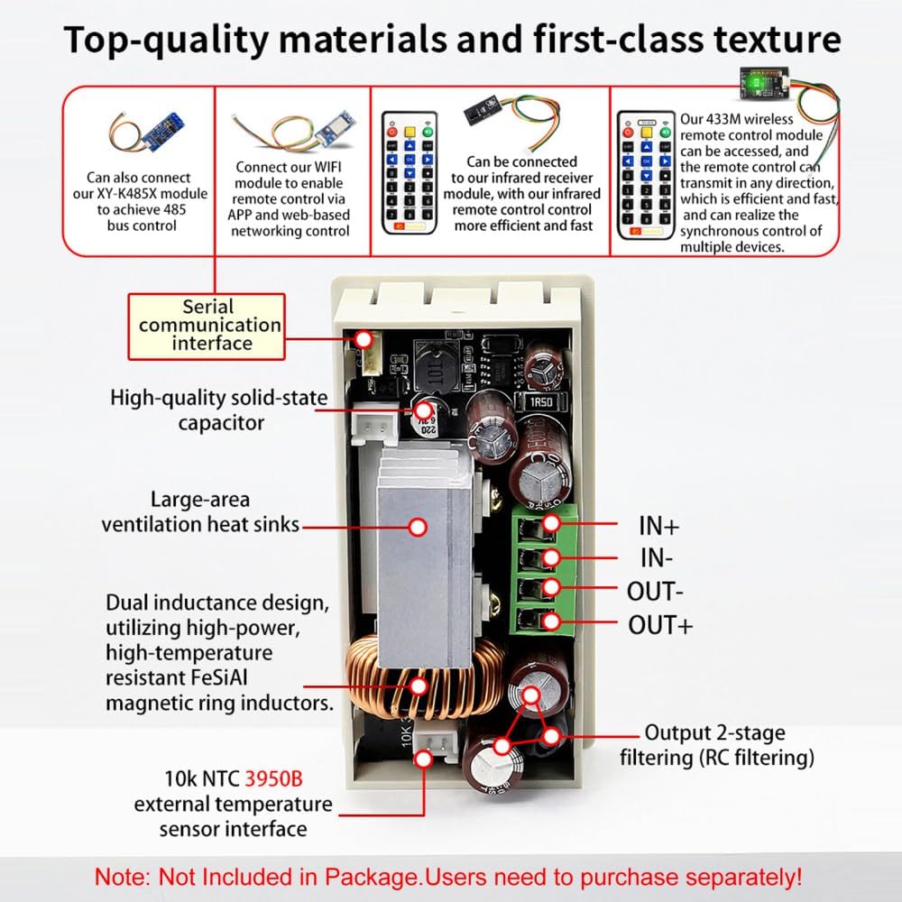
Figure 2: Internal components and external interfaces. Note: Remote control modules and temperature sensor are not included and must be purchased separately.
5. Setup and Installation
Proper installation is crucial for the safe and efficient operation of the module.
5.1 Physical Dimensions and Mounting
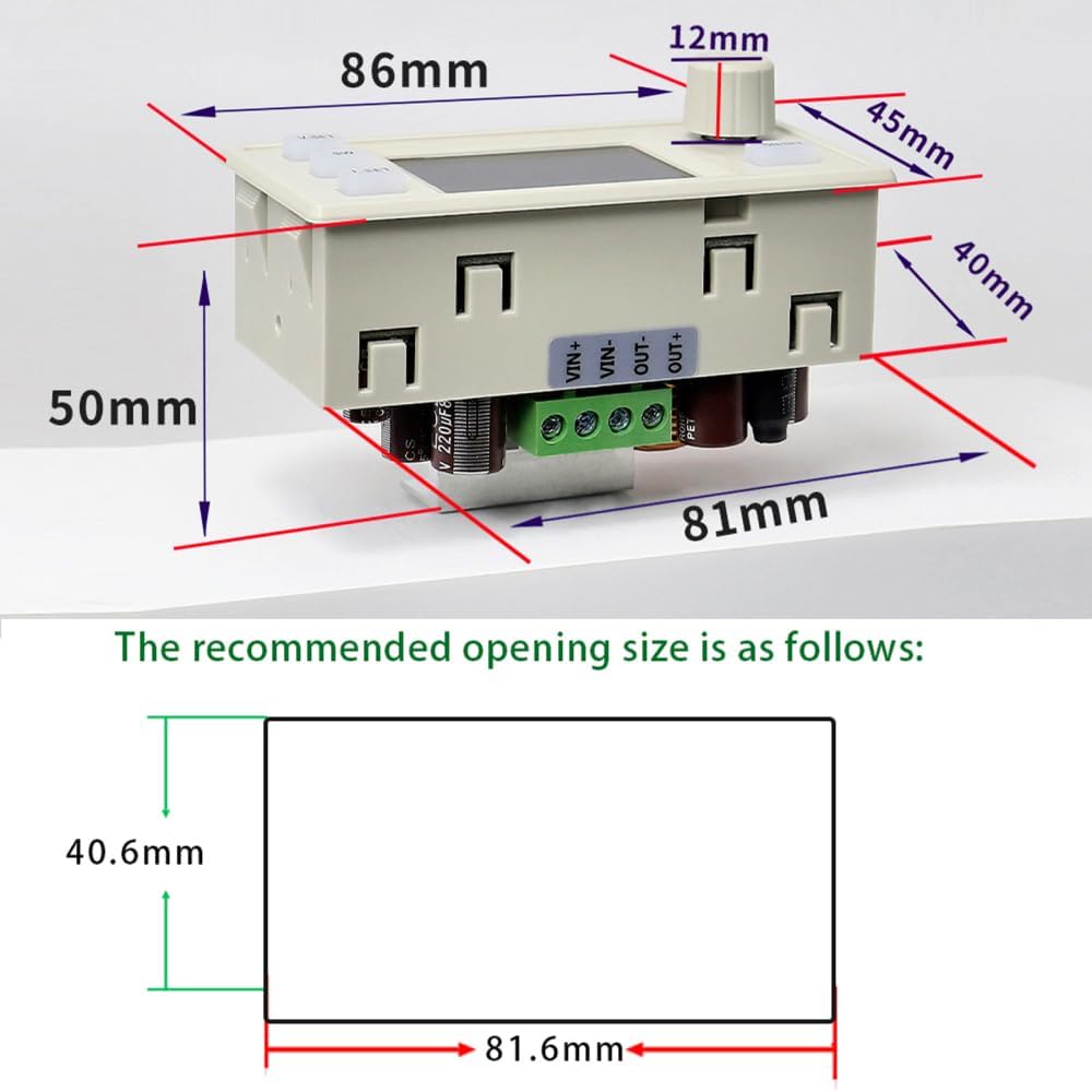
Figure 3: Module dimensions and recommended panel opening size for installation.
The module measures 86mm x 50mm x 45mm. For panel mounting, a recommended opening size of 81.6mm x 40.6mm is suggested.
5.2 Wiring Connections
Connect the input and output terminals as shown in the diagram below. Ensure correct polarity for all connections.

Figure 4: Example wiring for solar charging with an external temperature probe.
- Input (VIN+, VIN-): Connect your DC 12V-72V power source here.
- Output (OUT+, OUT-): Connect your load or battery here.
- NTC Temperature Probe Interface: For external temperature monitoring, connect a 10k NTC 3950B external temperature sensor (not included).
Important Safety Notes for Wiring:
- This is a DC power module; it cannot be connected to AC power.
- This is a step-down power supply module; the output voltage must always be lower than the input voltage.
- When using as a charger, connect the input power source before connecting the battery. Ensure the output voltage is set higher than the battery voltage.
- Ensure the input power source can supply more power than the connected load requires.
- The product does not have output reverse connection protection. Reversing the positive and negative terminals of the battery will damage the device.
- Battery charging requires specific knowledge. Non-professionals should not attempt to charge directly to prevent fire and explosion.
6. Operating Instructions
6.1 Basic Operation
- Power On: Connect the DC input power source (12V-72V) to the VIN+ and VIN- terminals. The LCD display will illuminate.
- Set Output Voltage: Short press the V-SET button. The voltage value on the display will blink. Rotate the Rotary Encoder to adjust the voltage. Short press the SW button to shift between digits. Press V-SET again to confirm and exit setting mode.
- Set Output Current (Current Limit): Short press the I-SET button. The current value will blink. Rotate the Rotary Encoder to adjust the current limit. Short press the SW button to shift between digits. Press I-SET again to confirm and exit setting mode.
- Enable Output: After setting voltage and current, short press the green ON/OFF button to enable the output. The 'ON' indicator will light up.
- Disable Output: Short press the green ON/OFF button again to disable the output.
- Switch Display Parameters: Short press the Rotary Encoder to cycle through different display parameters (e.g., input voltage, output voltage, current, power, capacity, energy, time).
- Lock/Unlock Parameters: Long press the Rotary Encoder to lock or unlock the current settings, preventing accidental changes.
- Clear Accumulated Values: Long press the green ON/OFF button to clear accumulated capacity (AH), energy (KWH), and time (H) data.
6.2 MPPT Solar Charging
The module supports MPPT solar charging. When connected to a solar panel and a battery (as shown in Figure 4), the module will automatically track the maximum power point of the solar panel to optimize charging efficiency.
- Connect the solar panel to the VIN+ and VIN- terminals.
- Connect the battery to the OUT+ and OUT- terminals.
- Ensure the output voltage is set appropriately for your battery type.
- An external temperature probe can be connected to the NTC interface to monitor battery temperature. The module will automatically stop charging if the battery temperature exceeds the set over-temperature protection limit.
7. Applications
- High-power LED constant current drive
- Battery charging (e.g., lead-acid, lithium-ion)
- Solar panel power conversion and charging
- Wind turbine power conversion
- General purpose adjustable power supply
- Instrument voltage display
- Circuit testing
- Various power conversion needs
8. Safety Precautions
- Always ensure correct input voltage polarity (VIN+ to positive, VIN- to negative).
- Always ensure correct output voltage polarity (OUT+ to positive, OUT- to negative). Reversing output polarity, especially with batteries, can cause severe damage.
- Do not connect the module to AC power sources. It is designed for DC input only.
- The output voltage must always be lower than the input voltage for proper buck (step-down) operation.
- Ensure adequate ventilation, especially during high-power operation, to prevent overheating. If the module becomes hot, reduce the output power.
- Do not exceed the maximum input voltage (72V), output current (6A), or output power (390W).
- Exercise caution when working with electrical circuits. If you are not familiar with electronics, seek professional assistance.
- Keep the module away from moisture, dust, and extreme temperatures.
9. Troubleshooting
- No Display/No Power: Check input voltage connections and ensure the input voltage is within the specified range (12V-72V).
- No Output: Ensure the output is enabled by short pressing the green ON/OFF button. Check if the output voltage is set correctly and is lower than the input voltage. Verify load connections.
- Output Voltage/Current Instability: Check for loose connections. Ensure the input power source is stable and can provide sufficient current.
- Over-temperature Protection Triggered: Reduce the load or ensure adequate cooling. Check for obstructions to the cooling fan.
- Protection Mechanism Activated: If any protection (e.g., OVP, OCP, OPP) is triggered, the module will stop output. Identify and resolve the underlying issue (e.g., excessive load, incorrect voltage setting) before re-enabling output.
10. Warranty and Support
DONGKER is committed to providing high-quality products and customer service. If you encounter any questions or issues with your XY-6506X Buck Module, please contact DONGKER customer support. We are dedicated to providing after-sales service until you are satisfied.