1. Introduction
The Fockety PN108 Digital Clamp Meter is a versatile and reliable instrument designed for accurate electrical measurements. It combines the functions of a clamp meter and a multimeter, allowing for non-contact AC/DC current measurement, as well as direct measurement of AC/DC voltage, resistance, capacitance, frequency, temperature, diode, continuity, and Non-Contact Voltage (NCV) detection. Its compact size, clear LCD display, and auto-ranging capabilities make it an essential tool for electricians, technicians, and DIY enthusiasts.
This manual provides detailed instructions for the safe and effective use of your PN108 Digital Clamp Meter. Please read it thoroughly before operation and keep it for future reference.
2. Safety Information
Always observe basic safety precautions when using this instrument to avoid personal injury or damage to the meter. Improper use can result in electric shock or damage to the meter.
- Do not apply voltage or current that exceeds the specified maximum limits.
- Use caution when working with voltages above 30V AC RMS, 42V peak, or 60V DC. These voltages pose a shock hazard.
- Before measuring current, ensure the circuit is de-energized and the clamp jaws are properly closed around a single conductor.
- Always disconnect the test leads from the circuit before changing functions.
- Do not operate the meter if it appears damaged or if the test leads are damaged.
- Ensure the battery cover is securely closed before operation.
- Do not use the meter in wet environments or in the presence of explosive gas or dust.
3. Product Overview
The PN108 Digital Clamp Meter is designed for ease of use and durability. Below is an overview of its main components and included accessories.
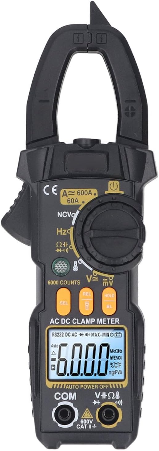
Figure 3.1: Front view of the PN108 Digital Clamp Meter, showing the clamp jaws, rotary dial, LCD display, and function buttons.

Figure 3.2: The PN108 Digital Clamp Meter along with its standard accessories, including test leads, a temperature probe, and a storage bag.
3.1. Main Components
- Clamp Jaws: For non-contact AC/DC current measurement.
- Rotary Dial: To select measurement functions.
- LCD Display: Shows measurement readings, units, and indicators.
- Function Buttons: Including SEL (Select), REL (Relative), HOLD (Data Hold), and BL (Backlight).
- Input Jacks: COM (Common), VΩHz (Voltage, Resistance, Frequency), and mA (for specific current measurements if applicable, though clamp meter primarily uses jaws for current).
- Flashlight: Integrated light for illuminating dark work areas.
3.2. Included Accessories
- 1 x Digital Clamp Meter (PN108)
- 1 x Temperature Test Line (K-type thermocouple)
- 2 x Test Pens (Red and Black Test Leads)
- 1 x Storage Bag
- 1 x English User Manual (This document)
4. Setup
4.1. Battery Installation
The PN108 Digital Clamp Meter requires 2 x AAA batteries (not included) for operation.
- Locate the battery compartment on the back of the meter.
- Use a screwdriver to open the battery compartment cover.
- Insert two AAA batteries, observing the correct polarity (+ and -) as indicated inside the compartment.
- Replace the battery compartment cover and secure it with the screw.
4.2. Connecting Test Leads
For voltage, resistance, capacitance, frequency, diode, and continuity measurements, connect the test leads:
- Insert the black test lead into the "COM" (Common) input jack.
- Insert the red test lead into the "VΩHz" input jack.
For temperature measurements, connect the temperature test line (K-type thermocouple) to the designated input terminals, observing polarity if indicated.
5. Operating Instructions
5.1. Power On/Off and Auto Shutdown
- To power on the meter, rotate the rotary dial from the "OFF" position to any desired measurement function.
- The meter features an automatic shutdown function. If there is no operation for a certain period (typically 15 minutes), the meter will automatically power off to conserve battery life. To reactivate, turn the rotary dial to "OFF" and then back to a function.
5.2. AC Current Measurement
The PN108 can measure AC current up to 600A without breaking the circuit.
- Rotate the dial to the "A~" (AC Current) position.
- Open the clamp jaws by pressing the trigger.
- Enclose only one conductor of the circuit within the clamp jaws. Ensure the jaws are fully closed.
- Read the AC current value on the LCD display.
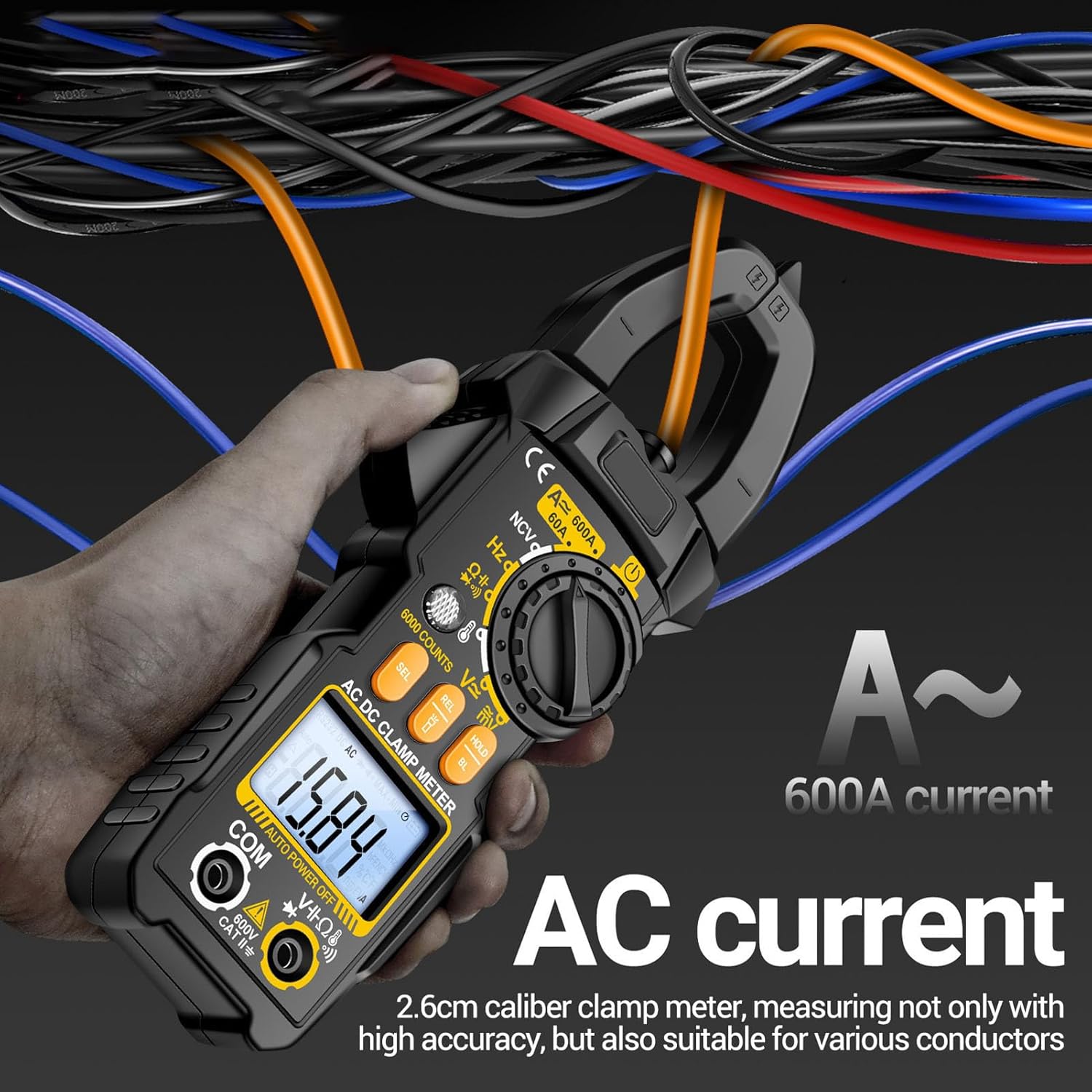
Figure 5.1: Measuring AC current by clamping around a single conductor. The meter displays the current value.
5.3. DC Current Measurement
The PN108 can measure DC current up to 600A, useful for automotive or battery applications.
- Rotate the dial to the "A=" (DC Current) position.
- Open the clamp jaws.
- Enclose only one DC conductor within the clamp jaws. Ensure the jaws are fully closed.
- Read the DC current value on the LCD display. Note the polarity indicated.

Figure 5.2: Measuring DC current, such as from a car battery, by clamping around a single wire.
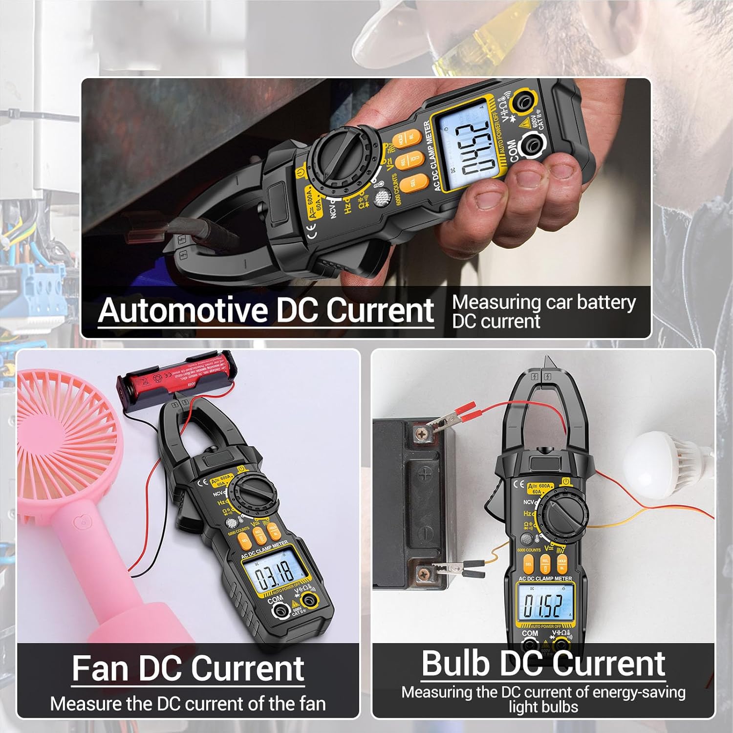
Figure 5.3: Examples of DC current measurement, including automotive battery current, fan current, and bulb current.
5.4. Voltage Measurement (AC/DC)
The meter can measure AC and DC voltage up to 600V.
- Connect the black test lead to "COM" and the red test lead to "VΩHz".
- Rotate the dial to the "V~" (AC Voltage) or "V=" (DC Voltage) position. The meter may auto-detect AC/DC.
- Touch the test probes to the circuit points where voltage is to be measured (in parallel with the load).
- Read the voltage value on the LCD display.
5.5. Resistance (Ω) Measurement
Measures resistance up to 20MΩ.
- Ensure the circuit is de-energized before measuring resistance.
- Connect the black test lead to "COM" and the red test lead to "VΩHz".
- Rotate the dial to the "Ω" (Resistance) position.
- Touch the test probes across the component or circuit where resistance is to be measured.
- Read the resistance value on the LCD display.
5.6. Continuity Test
Checks for an open or closed circuit.
- Ensure the circuit is de-energized.
- Connect the black test lead to "COM" and the red test lead to "VΩHz".
- Rotate the dial to the continuity/diode position (often indicated by a speaker icon). Press SEL if needed to select continuity.
- Touch the test probes across the circuit or component.
- A continuous beep indicates a good connection (low resistance). No beep indicates an open circuit.
5.7. Diode Test
Tests the forward voltage drop of a diode.
- Ensure the circuit is de-energized.
- Connect the black test lead to "COM" and the red test lead to "VΩHz".
- Rotate the dial to the continuity/diode position. Press SEL if needed to select diode test.
- Connect the red probe to the anode and the black probe to the cathode of the diode.
- Read the forward voltage drop on the display. Reverse the probes; an open circuit reading indicates a good diode.
5.8. Capacitance Measurement
Measures capacitance up to 99.99mF.
- Ensure the capacitor is fully discharged before testing.
- Connect the black test lead to "COM" and the red test lead to "VΩHz".
- Rotate the dial to the capacitance position (often indicated by a capacitor symbol).
- Touch the test probes across the capacitor terminals.
- Read the capacitance value on the LCD display.
5.9. Frequency (Hz) Measurement
Measures frequency up to 99.99kHz.
- Connect the black test lead to "COM" and the red test lead to "VΩHz".
- Rotate the dial to the frequency position (Hz).
- Touch the test probes across the circuit where frequency is to be measured.
- Read the frequency value on the LCD display.
5.10. Temperature Measurement
Measures temperature from 0℃ to 1000℃ (0℉ to 1832℉).
- Connect the temperature test line (K-type thermocouple) to the designated input terminals, observing polarity.
- Rotate the dial to the temperature position (℃/℉).
- Place the tip of the temperature probe on or near the object whose temperature is to be measured.
- Read the temperature value on the LCD display.

Figure 5.4: Measuring liquid temperature using the included temperature probe connected to the meter.
5.11. Non-Contact Voltage (NCV) Detection
Detects the presence of AC voltage without physical contact.
- Rotate the dial to the "NCV" position.
- Move the NCV sensor (located at the top of the meter) close to the conductor or outlet.
- If AC voltage is detected, the indicator light will flash red and the meter will emit an audible beep alarm. The intensity of the beeps and flashes may increase with stronger voltage.
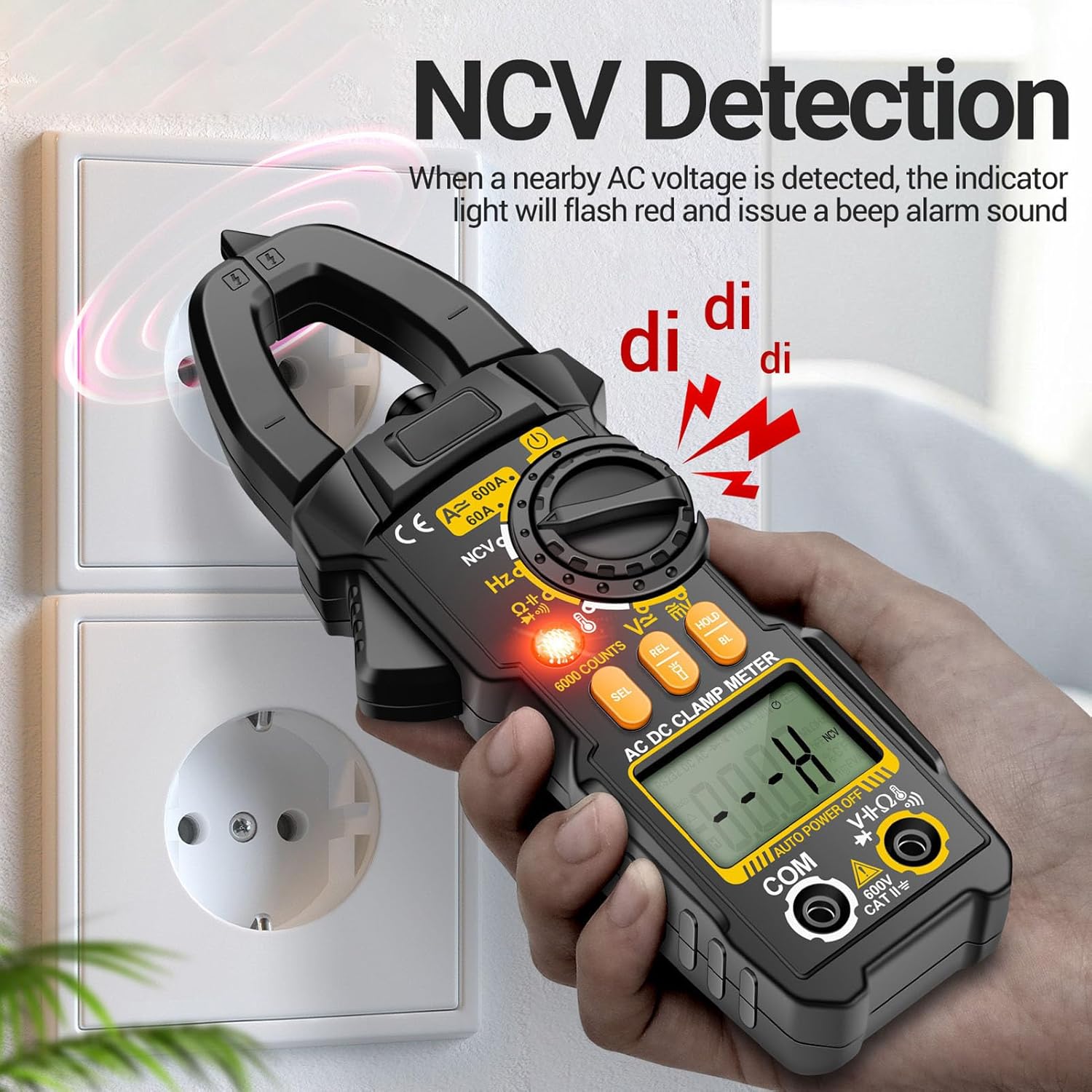
Figure 5.5: Demonstrating NCV detection near an electrical outlet. The meter indicates voltage presence with light and sound.
5.12. Special Functions
- HOLD Button: Press to freeze the current reading on the display. Press again to release.
- BL (Backlight) Button: Long press to turn on the LCD backlight for improved visibility in low-light conditions. Long press again to turn off.
- Flashlight: Long press the flashlight button (usually located near the clamp jaws or on the side) to turn on the integrated flashlight. This assists in illuminating dark work areas and improving safety. Long press again to turn off.
- REL (Relative) Button: Used for relative measurement, displaying the difference between the current reading and a stored reference value.
- SEL (Select) Button: Used to toggle between functions within a single rotary dial position (e.g., AC/DC voltage, continuity/diode).
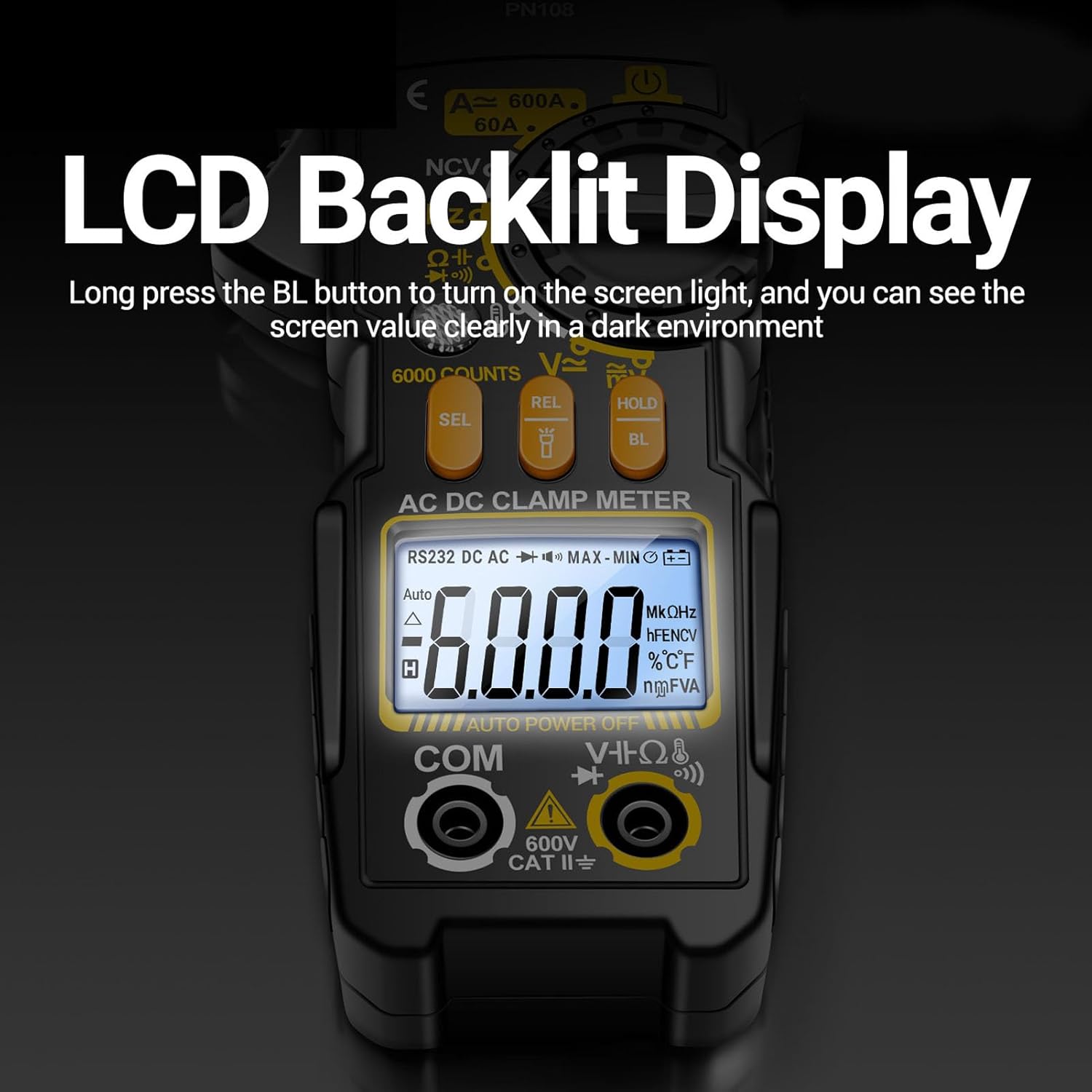
Figure 5.6: The PN108's LCD display with backlight activated, ensuring clear readings in dark environments.

Figure 5.7: The integrated flashlight on the PN108, providing illumination for measurements in dimly lit spaces.
6. Maintenance
6.1. Cleaning
Wipe the meter's casing with a damp cloth and mild detergent. Do not use abrasives or solvents. Keep the input jacks free of dust and debris.
6.2. Battery Replacement
When the low battery indicator appears on the display, replace the batteries promptly to ensure accurate readings. Follow the battery installation steps in Section 4.1.
6.3. Storage
If the meter is not to be used for an extended period, remove the batteries to prevent leakage. Store the meter in its storage bag in a cool, dry place, away from direct sunlight and extreme temperatures.
7. Troubleshooting
If you encounter issues with your PN108 Digital Clamp Meter, refer to the following common problems and solutions:
| Problem | Possible Cause | Solution |
|---|---|---|
| Meter does not power on. | Dead or incorrectly installed batteries. | Check battery polarity; replace batteries. |
| No reading or "OL" (Overload) displayed. | Measurement range exceeded, open circuit, or incorrect function selected. | Ensure correct function is selected. Check circuit for continuity. For current, ensure only one conductor is clamped. |
| Inaccurate readings. | Low battery, dirty test leads/jacks, or external interference. | Replace batteries. Clean test leads and input jacks. Move away from strong electromagnetic fields. |
| Continuity buzzer not working. | Open circuit or function not selected. | Ensure circuit is closed. Select continuity function using SEL button if necessary. |
8. Specifications
Below are the technical specifications for the PN108 Digital Clamp Meter:
| Parameter | Range / Value | Accuracy |
|---|---|---|
| Model | PN108 | N/A |
| Material | ABS | N/A |
| Battery Type | 2 x AAA battery (not included) | N/A |
| AC Voltage | 0mV-600V | ± (1.2%+5) |
| DC Voltage | 0mV-600V | ± (1.0%+5) |
| AC Current | 0A-600A | ± (4.0%+20) |
| DC Current | 0A-600A | ± (2.0%+8) |
| Resistance | 0Ω-20MΩ | ± (1.2%+3) |
| Capacitance | 0nF-99.99mF | ± (5.0%+5) |
| Frequency | 0Hz-99.99kHz | ± (0.3%+5) |
| Temperature | 0℃-1000℃ (1℃ resolution) / 0℉-1832℉ (1℉ resolution) | ± (1.9%+5) for ℃ / ± (1.9%+6) for ℉ |
| NCV | Yes | N/A |
| Diode Test | Yes | N/A |
| Buzzer (Continuity) | Yes | N/A |
| Data Retention | Yes | N/A |
| Screen Backlight | Yes | N/A |
| Flashlight Lighting | Yes | N/A |
| Low Power Indicator | Yes | N/A |
| Maximum Count | 6000 Count | N/A |
| Automatic Shutdown | Yes (if no operation) | N/A |
| Product Size | Approx. 195 x 69.5 x 35mm / 7.67 x 2.73 x 1.37in | N/A |
| Item Model Number | Fockety10ov2ftd9b | N/A |
9. Warranty and Support
For information regarding warranty coverage, technical support, or service, please refer to the manufacturer's official website or contact their customer service department. Details are typically provided with your purchase documentation or on the product packaging.