Introduction
This manual provides instructions for the installation, operation, and maintenance of the LiftMaster 050DCTBFLKMC Logic Control Board Replacement Kit. This kit is designed to replace existing logic boards in compatible garage door openers, enabling lock-capable functionality.
The 050DCTBFLKMC is a Bluetooth Enabled Receiver Logic Board Replacement Kit. It is intended for use with various LiftMaster and Chamberlain Lock Capable DC Belt Drive and Chain Drive Garage Door Openers that feature enhanced myQ Technology. The unit will have a yellow learn button. Always verify compatibility by checking your existing installation manual or replacement parts diagram before proceeding with the replacement.
Safety Information
WARNING: To prevent serious injury or death, always disconnect power to the garage door opener before performing any service or maintenance. Garage door springs are under extreme tension and can cause serious injury. Do not attempt to adjust, repair, or remove components connected to the garage door springs.
- Ensure the garage door opener is unplugged or the circuit breaker is off before beginning installation.
- Wear appropriate safety gear, including safety glasses.
- Follow all local electrical codes and regulations.
- If you are unsure about any step, consult a qualified technician.
Package Contents
The LiftMaster 050DCTBFLKMC Replacement Logic Control Board kit typically includes:
- One (1) 050DCTBFLKMC Logic Control Board
- Installation Manual (this document serves as a guide)
- New sticker with Bluetooth Device ID (for myQ pairing)
Note: Additional components such as garage door locks (e.g., LiftMaster 841LM) are sold separately and are required to utilize the lock-capable function.
Setup and Installation
This section outlines the steps for replacing your existing logic board with the 050DCTBFLKMC and setting up the lock-capable function.
1. Preparation
- Disconnect Power: Unplug the garage door opener from the electrical outlet or turn off the circuit breaker.
- Access Existing Board: Open the cover of your garage door opener to access the existing logic board.
- Document Connections: Before disconnecting any wires, take clear photos or make a diagram of all existing wire connections to the old logic board. This will aid in reconnecting wires to the new board.
2. Logic Board Replacement
- Remove Old Board: Carefully disconnect all wires and mounting screws securing the old logic board. Remove the old board.
- Install New Board: Position the new 050DCTBFLKMC logic board in place and secure it with the appropriate screws.
- Reconnect Wires: Using your documented connections, carefully reconnect all wires to the corresponding terminals on the new logic board. Ensure all connections are secure.
- Prepare for Lock Solenoid Connectors (if applicable): If you are installing garage door locks (e.g., LiftMaster 841LM), you may need to create openings in the existing plastic cover for the lock solenoid connectors. Tools like a Dremel or RotoZip can be used for this purpose.
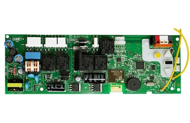
Image: The LiftMaster 050DCTBFLKMC Logic Control Board. This image shows the compact design of the replacement board, which integrates into compatible garage door opener units.
3. Lock Installation (Optional, if adding 841LM locks)
If you are installing LiftMaster 841LM automatic garage door locks, follow the instructions provided with the locks for mounting them to the door tracks. Run the lock cables to the new logic board and plug them into the designated connectors on the back of the board.
4. Power On and Initial Setup
- Restore Power: Plug the garage door opener back into the electrical outlet or turn on the circuit breaker.
- myQ App Re-pairing: You will need to re-pair the new logic board with the myQ app on your smartphone and reconnect it to your Wi-Fi network. Use the new sticker provided with the logic board, which contains the Bluetooth Device ID, to identify the correct board during the pairing process.
- Adjust Travel Limits: Follow the instructions in the small manual that came with the logic board (or your garage door opener manual) to adjust the door's up and down travel limits. This is a critical step for proper and safe operation.
Operating Instructions
Once the 050DCTBFLKMC logic board and any optional locks are installed and configured, the system will operate as follows:
- Automatic Locking: When the garage door is closed, the locks (if installed) will automatically engage, securing the door.
- Automatic Unlocking: When you activate the garage door opener (via remote, wall control, or myQ app) to open the door, the locks will automatically disengage before the door begins to move upwards.
- myQ Control: The myQ app allows for remote monitoring and control of your garage door opener, including the lock status.
Maintenance
The 050DCTBFLKMC logic control board is designed for long-term reliability with minimal maintenance. However, regular checks of your garage door opener system are recommended:
- Visual Inspection: Periodically inspect the logic board and all wiring for any signs of damage, loose connections, or corrosion.
- Cleanliness: Keep the garage door opener unit clean and free from dust, debris, and insects, which can interfere with electronic components.
- Functionality Test: Regularly test the garage door opener's safety features, including the auto-reverse mechanism and safety sensors, as per your opener's main manual.
- Lock Mechanism (if installed): If using automatic locks, ensure they move freely and are not obstructed. Lubricate moving parts of the lock mechanism as recommended by the lock manufacturer.
Troubleshooting
If you encounter issues after installing the 050DCTBFLKMC logic board, consider the following:
- Board Not Working:
- Ensure power is connected and the circuit breaker is on.
- Double-check all wire connections to the logic board against your documentation. Loose or incorrect wiring is a common cause of malfunction.
- Verify that the logic board is compatible with your specific garage door opener model. Refer to your opener's manual.
- Door Not Opening/Closing Properly:
- Re-adjust the travel limits as described in the "Setup and Installation" section.
- Check safety sensors for obstructions or misalignment.
- Locks Not Engaging/Disengaging:
- Ensure the lock cables are securely connected to the logic board.
- Verify that the locks themselves are properly installed and free of obstructions.
- Confirm that the travel limits are correctly set, as the locks rely on the door's position.
- myQ App Connectivity Issues:
- Ensure your Wi-Fi network is active and the signal is strong in the garage.
- Repeat the myQ app re-pairing process using the new Bluetooth Device ID.
- Consult the myQ app's help section or LiftMaster support for specific connectivity troubleshooting.
For further assistance, refer to the original garage door opener manual or contact LiftMaster customer support.
Specifications
| Feature | Detail |
|---|---|
| Model Number | 050DCTBFLKMC |
| Compatibility | Various LiftMaster and Chamberlain Lock Capable DC Belt Drive and Chain Drive Garage Door Openers with enhanced myQ Technology (yellow learn button) |
| Connectivity | Bluetooth Enabled Receiver, myQ Technology |
| Included Components | Control Board |
| Dimensions | Approximately 7 x 3 x 1 inches |
| Weight | Approximately 1 pound |
Warranty and Support
This LiftMaster product is covered by a manufacturer's warranty. Please refer to the warranty information provided with your original garage door opener or visit the official LiftMaster website for details regarding warranty terms and conditions for replacement parts.
For technical support, troubleshooting assistance, or to purchase additional genuine LiftMaster parts, please visit the LiftMaster Store on Amazon or the official LiftMaster website.


