1. Product Overview
The xicoolee 2.42-inch OLED Display Module is a high-quality display solution featuring a 128x64 pixel resolution. It supports both SPI and I2C communication protocols, offering flexible integration into various embedded systems. Designed with an SSD1309 driver chip, this module provides clear visuals and efficient power consumption. Its compact design and ultra-narrow bezel make it suitable for projects with limited space. This module is compatible with popular development platforms such as Raspberry Pi, Arduino, STM32, and ESP32.
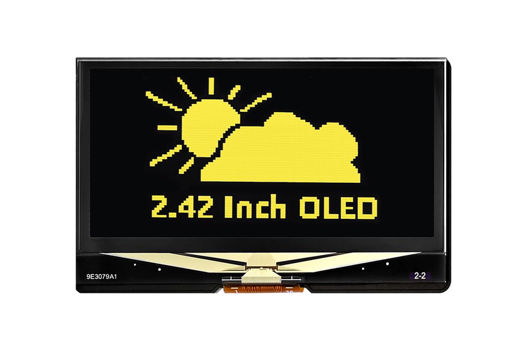
Figure 1: Front view of the 2.42-inch OLED Display Module.
2. Package Contents
Verify that all items listed below are included in your package:
- 1 x 2.42inch OLED Display Module
- 1 x GH1.25 7PIN cable

Figure 2: Package contents including the OLED display and connection cable.
3. Specifications
Detailed technical specifications for the 2.42-inch OLED Display Module:
| Feature | Description |
|---|---|
| Display Size | 2.42 inches |
| Resolution | 128 x 64 pixels |
| Driver Chip | SSD1309 |
| Communication Interface | SPI (4-wire), I2C |
| Voltage Translator | TXS0108PWR |
| Supply Voltage | 3.3V / 5V |
| Display Color | Yellow (This specific model) |
| Compatible Devices | Raspberry Pi, Arduino, STM32, ESP32 |
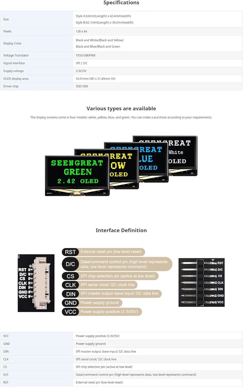
Figure 3: Product specifications table.
4. Setup Guide
This section outlines the steps for connecting your OLED display module to a development board.
4.1 Interface Selection (SPI/I2C)
The module features a switch on the back to select between SPI and I2C communication modes. Ensure this switch is set to your desired communication protocol before connecting the module to your development board.
4.2 Pin Definitions and Connections
Refer to the pinout diagram and table below for correct wiring. The provided GH1.25 7PIN cable can be used for connection.

Figure 4: Interface Definition and Pinout.
| Pin | Function |
|---|---|
| VCC | Power supply positive (3.3V/5V) |
| GND | Power supply ground |
| DIN | SPI master output slave input / I2C data line |
| CLK | SPI serial clock / I2C clock line |
| CS | SPI chip selection pin (active at low level) |
| D/C | Data/command control pin (high level represents data, low level represents command) |
| RST | External reset pin (low level reset) |
For I2C communication, typically only VCC, GND, DIN (SDA), and CLK (SCL) pins are required. For SPI, all 7 pins are generally used.
5. Operating Instructions
To operate the OLED display, you will need to program your development board using appropriate libraries and example code.
5.1 Software Setup
- Install Development Environment: Ensure you have the correct IDE installed for your chosen platform (e.g., Arduino IDE for Arduino/ESP32, Python with libraries for Raspberry Pi).
- Install Display Library: This module uses the SSD1309 driver. While dedicated SSD1309 libraries exist, many users have successfully used SSD1306 libraries (e.g., Adafruit SSD1306 library) with minor modifications or directly, as the drivers are often compatible. Search for "SSD1309 library for [Your Platform]" or "SSD1306 library for [Your Platform]".
- Obtain Example Code: Comprehensive online resources and example codes are available for Raspberry Pi, Arduino, ESP32, and Jetson Nano. These examples demonstrate how to initialize the display, draw text, shapes, and images.
5.2 Basic Display Operation
Once the software is set up and the module is correctly wired, you can upload your code to the development board. The code will typically:
- Initialize the display with the correct communication protocol (SPI or I2C) and address (for I2C).
- Clear the display buffer.
- Draw desired content (text, pixels, lines, rectangles, bitmaps) into the buffer.
- Update the display to show the content from the buffer.
6. Maintenance
To ensure the longevity and optimal performance of your OLED display module, follow these maintenance guidelines:
- Handle with Care: Avoid applying excessive pressure to the display surface. OLED screens are delicate.
- Prevent Static Discharge: Always handle the module in an anti-static environment or use appropriate grounding measures to prevent damage from electrostatic discharge (ESD).
- Keep Clean: Use a soft, dry, lint-free cloth to gently clean the display surface. Avoid abrasive cleaners or solvents.
- Environmental Conditions: Store and operate the module within recommended temperature and humidity ranges. Avoid extreme temperatures and high humidity.
- Power Off Before Connecting/Disconnecting: Always disconnect power from your development board before making or changing any connections to the OLED module.
7. Troubleshooting
If you encounter issues with your OLED display module, consider the following troubleshooting steps:
- Display Not Activating/Blank Screen:
- Check Connections: Verify all pins (VCC, GND, data, clock, etc.) are securely connected to the correct pins on your development board. Loose connections are a common cause.
- Power Supply: Ensure the module is receiving the correct voltage (3.3V or 5V). Some setups may require 5V for proper operation.
- Interface Switch: Confirm the SPI/I2C selector switch on the back of the module is set to match the communication protocol used in your code.
- I2C Address: If using I2C, ensure your code uses the correct I2C address for the SSD1309 driver (common addresses are 0x3C or 0x3D). Run an I2C scanner sketch if available for your platform.
- Library Compatibility: While the module uses SSD1309, many SSD1306 libraries work. If one library fails, try another or specifically search for SSD1309 compatible libraries.
- Reset Pin: Ensure the RST pin is correctly handled in your code (e.g., pulled low then high during initialization).
- Garbled or Incomplete Display:
- Buffer Size: Ensure your display library is configured for 128x64 resolution.
- Data Rate (SPI): For SPI, check if the data rate is appropriate for your microcontroller.
- Code Logic: Review your drawing and display update logic. Ensure you are clearing the buffer and updating the display correctly.
- Module Interfering with Other Devices (e.g., RTC module):
- I2C Conflicts: If using I2C, ensure there are no address conflicts with other I2C devices on the bus.
- Pull-up Resistors: Verify that appropriate pull-up resistors are present on the I2C lines (SDA, SCL) if not provided by your development board or other devices.
8. Warranty and Support
This xicoolee product is covered by a standard manufacturer's warranty against defects in materials and workmanship. For specific warranty terms and conditions, please refer to the product packaging or contact xicoolee customer support.
For technical assistance, troubleshooting, or further inquiries, please visit the xicoolee store on Amazon or contact their customer service directly. Online resources and community forums for Raspberry Pi, Arduino, and other compatible platforms also offer extensive support and example projects.
Online Resources: Visit the xicoolee Store on Amazon