1. Introduction

Figure 1.1: The cekay Universal Adjustable Mounting Pole, including the J-mount pole, mounting bracket, screws, and wrench.
This manual provides comprehensive instructions for the installation, operation, and maintenance of the cekay Universal Adjustable Mounting Pole, Model 032. This J-mount is designed for secure and versatile outdoor installation of various devices such as 4G/5G antennas, WiFi equipment, TV antennas, satellite dishes, weather stations, and cell phone signal boosters. Please read these instructions carefully before installation to ensure proper setup and optimal performance.
2. Package Contents
Verify that all components listed below are included in your package.

Figure 2.1: All components included in the package. This includes the main J-pole sections, mounting bracket, screws, and a screw sleeve wrench.
- Adjustable J-Pole (main sections)
- Mounting Bracket
- ST8*50mm Stainless Steel Self-Tapping Screws (4 pieces)
- Plastic Anchors (4 pieces)
- Screw Sleeve Wrench
- Locking Pin (pre-installed or separate)
3. Setup and Installation
The cekay Universal Adjustable Mounting Pole offers flexible installation options for various surfaces.
3.1. Component Overview and Dimensions
Familiarize yourself with the pole's design and dimensions for proper planning. The pole features a 1 1/4" outer diameter and is constructed from 1.5mm thick durable iron. The reinforced mounting bracket is 2mm thick.

Figure 3.1.1: Detail of the pole's diameter and thickness, highlighting the lock pin mechanism.

Figure 3.1.2: Dimensional drawing of the mounting bracket, indicating its 2mm thickness for durability and the position of the lock pin.
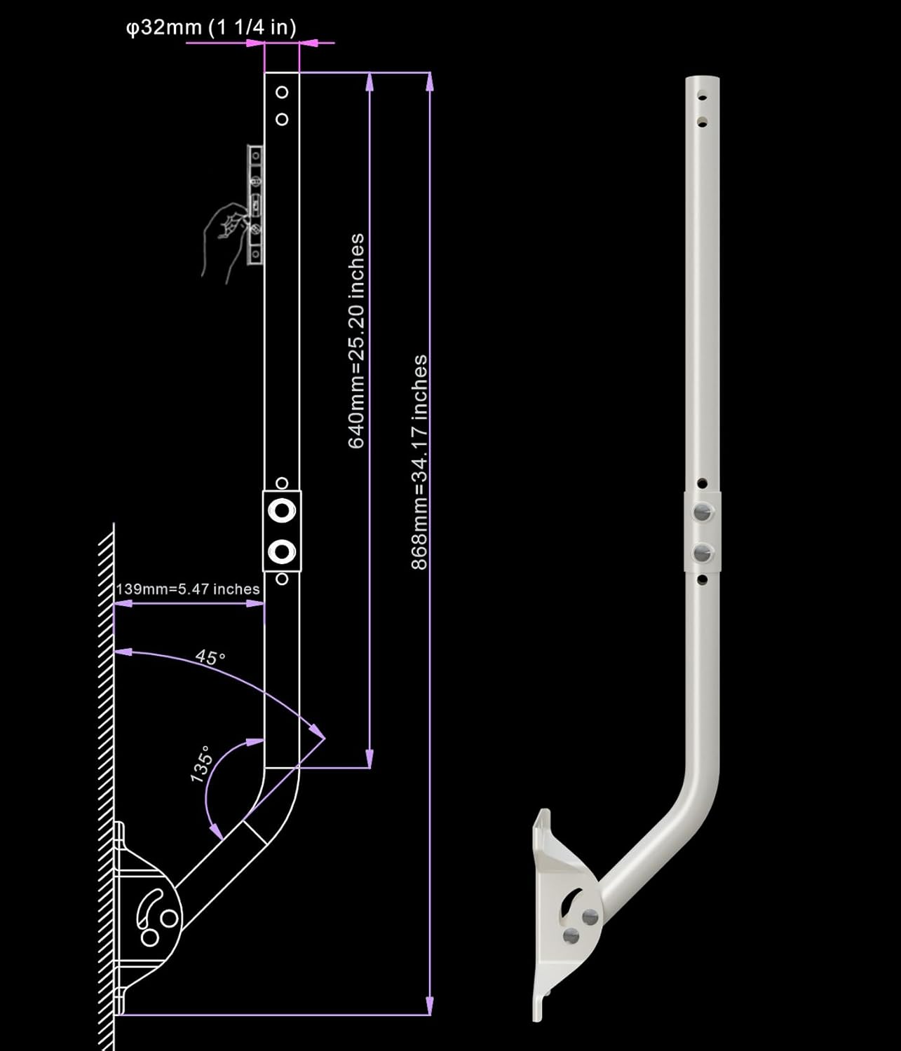
Figure 3.1.3: Technical drawing illustrating the J-pole configuration with key dimensions.

Figure 3.1.4: Technical drawing illustrating the straight pole configuration with key dimensions.
3.2. Choosing an Installation Location
The mounting pole can be installed on various surfaces including walls, eaves, or roofs. Consider the following when selecting a location:
- Signal Reception: Choose a location that provides the clearest line of sight for optimal signal reception for your antenna or device.
- Structural Integrity: Ensure the mounting surface is structurally sound and can support the weight of the pole and the attached device, especially in windy conditions.
- Accessibility: Select a location that allows for safe installation and future maintenance, if required.
3.3. Mounting the Bracket
- Position the mounting bracket on your chosen surface. Mark the drilling points through the bracket's holes.
- Drill pilot holes at the marked locations. For masonry or concrete, use appropriate drill bits and insert the plastic anchors.
- Secure the mounting bracket using the provided ST8*50mm stainless steel self-tapping screws. Use the screw sleeve wrench for easier installation.
3.4. Assembling the Pole
The J-pole design is reversible, allowing for flexible wall standoff distance adjustments. You can configure it as a J-mount or a straight pole depending on your needs.
- Attach the pole sections to the mounting bracket. The bracket has two fixing points for horizontal and vertical surfaces.
- Insert the locking pin through the designated holes to secure the pole's angle and prevent rotation. Ensure the pin is fully engaged.
- For extended reach, an optional 16 1/2" mast extension (sold separately) can be added to enhance vertical height and horizontal clearance.

Figure 3.4.1: Illustration of various installation modes, demonstrating the pole's adaptability for different mounting scenarios.

Figure 3.4.2: Visual examples of the mounting pole in use, installed on both a roof and a wall, supporting a satellite dish.

Figure 3.4.3: Example of a Starlink satellite dish mounted on the adjustable pole.
4. Operation
Once installed, the mounting pole allows for directional adjustment to optimize signal reception.
- Adjustable Direction: The mounting pole can rotate up to 180° to achieve the optimal reception angle for your device. Loosen the securing bolts on the bracket, adjust the pole to the desired direction, and then firmly tighten the bolts to secure its position.
- Locking Pin: The integrated locking pin provides additional stability and prevents unwanted movement of the pole once the desired angle is set. Ensure it is properly engaged after adjustment.
5. Maintenance
The cekay mounting pole is constructed from durable, weatherproof materials designed for outdoor use. Minimal maintenance is required.
- Periodic Inspection: Annually, or after severe weather events, inspect all mounting points, screws, and the pole itself for any signs of loosening, corrosion, or damage.
- Cleaning: If necessary, clean the pole with a damp cloth to remove dirt or debris. Avoid abrasive cleaners that could damage the powder-coated finish.
- Tighten Fasteners: Re-tighten any loose screws or bolts to ensure the pole remains securely mounted.
6. Troubleshooting
This section addresses common issues that may arise during or after installation.
- Pole is not stable:
- Ensure all mounting screws are securely tightened.
- Verify that the locking pin is fully engaged in the desired position.
- Check the structural integrity of the mounting surface.
- Difficulty adjusting pole angle:
- Loosen the securing bolts on the bracket sufficiently before attempting to rotate the pole.
- Ensure no debris is obstructing the rotation mechanism.
- Poor signal reception for attached device:
- Re-adjust the pole's direction to find the optimal signal path.
- Ensure there are no new obstructions (e.g., trees, buildings) blocking the signal.
- Consult the instruction manual for the device attached to the pole for specific signal optimization tips.
7. Specifications
| Feature | Detail |
|---|---|
| Model Number | 032 |
| Brand | cekay |
| Mounting Type | Pole Mount |
| Material | Alloy Steel |
| Finish Type | Powder Coated |
| Color | White |
| Item Weight | 4.09 pounds |
| Product Dimensions | 1 x 1 x 1 inches (packaged) |
| Pole Outer Diameter | 1 1/4" (32mm) |
| Pole Thickness | 1.5mm |
| Bracket Thickness | 2mm |
| Arm Length (33.25" variant) | 33 1/4" |
| Included Components | Mounting Bracket and Hardware |
8. Warranty Information
The cekay Universal Adjustable Mounting Pole comes with a 1 Year Warranty from the date of purchase. This warranty covers manufacturing defects and material flaws under normal use. It does not cover damage resulting from improper installation, misuse, accidents, or unauthorized modifications. Please retain your proof of purchase for warranty claims.
9. Customer Support
For any questions, concerns, or assistance with your cekay Universal Adjustable Mounting Pole, please contact our professional customer support team. We are committed to ensuring your complete satisfaction.
Contact information can typically be found on the product packaging or the official cekay website.