1. Introduction
The PDDAXLQUE DX-LR02-A is a low-power LoRa wireless transceiver module designed for long-range data transmission. It features an ASR6601 SOC chip and supports UART serial communication, enabling transparent data transfer between devices. This module is ideal for various applications requiring extended communication ranges, such as smart home systems, industrial monitoring, and DIY projects with microcontrollers like Arduino, Raspberry Pi, or ESP32.
This manual provides detailed instructions for the setup, operation, and configuration of your DX-LR02-A module using AT commands.

Figure 1: The DX-LR02-A LoRa wireless transceiver module shown with its accompanying antenna. The module is blue with a metal shield, and the antenna is black with a right-angle SMA connector.
2. Key Features
The DX-LR02-A module offers a robust set of features for reliable long-range wireless communication:
- ASR6601 SOC Chip: Integrated 32-bit ARM STAR Core for efficient processing.
- Operating Frequency: Supports 410-493MHz, with a maximum frequency of 48MHz, ensuring global compatibility.
- UART Serial Communication: Enables transparent data transmission with configurable baud rates (1200 to 128000).
- AT Command Set: Extensive AT commands for easy configuration of module parameters such as mode, frequency, MAC address, bandwidth, spreading factor, and coding rate.
- High Power PA: Output power up to +22dBm for extended range.
- High Sensitivity: Maximum receiver sensitivity of -138dBm.
- Power Management: Supports sleep mode and wake-on-air mode for power efficiency.
- Long Range: Line-of-sight distance up to 5km in open environments.
- Operating Voltage: 3.3V-5.5V (typical 5V).
- Compact Size: Module dimensions are 36(L)x16.5(W)x4(H)mm.
- Certifications: CE, FCC, and RoHS compliant, ensuring product safety and reliability.

Figure 2: An illustration detailing the key features and dimensions of the LR02-433T22D module, including its ASR6601 chip, operating frequency range, power output, and physical size.
3. Setup and Installation
3.1 Pinout and Wiring
Proper connection of the module to your development board or system is crucial for correct operation. Ensure that the module and any adapter board are inserted with correct positive and negative pins to prevent damage.

Figure 3: Detailed wiring diagrams for the LR01 module (similar to LR02) and an adapter plate. It shows the pin assignments for M0, M1, PXD, TXD, AUX, VCC, and GND, along with an example wiring configuration.
The pin definitions are as follows:
- M0, M1: Reserved, customizable IO ports.
- UART_RX (PXD): UART Receive pin.
- UART_TX (TXD): UART Transmit pin.
- AUX: Auxiliary pin (refer to detailed documentation for specific usage).
- VCC: Power Supply input (3.3V-5.5V).
- GND: Ground.
3.2 Indicator Status
The module features an indicator light to show its operational status:
- Working status: Red light blinking.
- Hibernation mode: Light off when hibernating, red light flashing when waking up.
4. Operating Instructions
4.1 Serial Communication
The DX-LR02-A module utilizes UART serial communication for transparent data transmission. This means data sent to the module's UART input will be wirelessly transmitted and output via the UART of a receiving module, and vice-versa. The module supports various baud rates:
- 1200 bps
- 2400 bps
- 9600 bps (Default)
- 19200 bps
- 38400 bps
- 57600 bps
- 115200 bps
- 128000 bps
Ensure that the baud rate of the module matches the baud rate of the connected device for successful communication.
4.2 AT Command Settings
The module can be configured using a set of AT commands. These commands allow you to query and set various parameters without needing to write complex LoRa programming. To enter AT command mode, typically send "+++" via serial. To exit, send "AT+QUIT" or similar (refer to full AT command documentation).
Common AT commands include:
| AT Command | Command Description |
|---|---|
| AT | Test (Response OK) |
| +++ | Enter/Exit AT command mode |
| AT+BAUD | Set/query baud rate |
| AT+MODE | Set/query operating mode |
| AT+SLEEP | Set/query power consumption mode |
| AT+CHANNEL | Set/query working channels |
| AT+MAC | Set/query device address |
| AT+POWER | Set/query transmit power |
| AT+IQ | Setting the IQ signal flip-flop |
For a complete list of AT commands and their detailed usage, please refer to the product's technical documentation package.
4.3 Working Modes
The DX-LR02-A module supports various communication modes to suit different application needs:
- Module and Module Transparent Transmission: In this mode, both the sender and receiver modules must be configured to the same channel to exchange data. Data is transmitted transparently without additional addressing.
- Module and Module Fixed-Point Transmission: This mode allows communication with specific modules by including an address and channel in the data format (e.g., hexadecimal: receiving address + receiving channel + data).
- Module and Module Broadcast Transmission: This mode enables sending data to all modules configured to a designated channel. The data format includes the receiver channel and the data (e.g., hexadecimal: receiver channel + data).

Figure 4: Diagrams illustrating the three primary working modes of the LoRa module: transparent transmission, fixed-point transmission with addressing, and broadcast transmission to a designated channel.
For detailed instructions on configuring these modes and using serial port testing software, refer to the product information packages and the DX-LR02-433T22D Module Serial Port UART Guide.

Figure 5: A screenshot of the UART Assistant Tools software, demonstrating how to configure the LoRa module's parameters suchs as port, baud rate, transmit mode, channel, address, and power settings using AT commands.
5. Application Scenarios
The DX-LR02-A module is suitable for a wide range of applications requiring long-distance serial data transmission, including but not limited to:
- Remote data acquisition in homes (e.g., from living room to basement or yard).
- Agricultural monitoring on pastures and farms.
- Industrial automation and monitoring within industrial parks.
- DIY projects involving long-distance motor control.
- Integration with microcontrollers such as Arduino, Raspberry Pi, or ESP32 for custom wireless solutions.
6. Technical Specifications
Below are the detailed technical specifications for the DX-LR02-A module and its antenna:
6.1 Module Specifications
| Parameter | Value |
|---|---|
| Chip Model | ASR6601 |
| Communication Interface | UART |
| Firing Power | 0 ~ +22dBm |
| Communication Distance | Visible distance up to 5km (open area) |
| Frequency Band | 410-493MHz |
| AT Instruction | Simple AT instruction set available |
| Transmission Method | Transparent, Fixed-point, Broadcast |
| Operating Temperature | -40°C ~ +85°C |
| Operating Voltage | 3.3V-5.5V (Typical 5V) |
| Modulation Method | Spread Spectrum Modulation |
| Sensitivity | -138dBm |
| RF Input Impedance | 50Ω |
| Module Dimensions | 36(L)x16.5(W)x4(H)mm |
6.2 Antenna Specifications
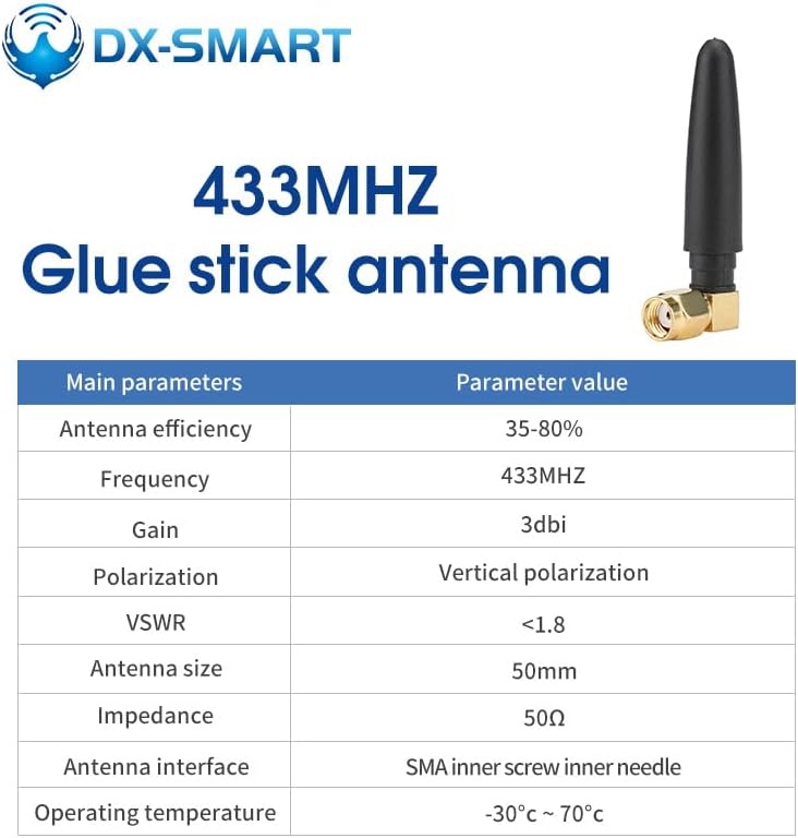
Figure 6: A visual representation of the 433MHz glue stick antenna, accompanied by a table listing its main parameters such as frequency, gain, polarization, and impedance.
| Parameter | Value |
|---|---|
| Antenna Efficiency | 35-80% |
| Frequency | 433MHz |
| Gain | 3dBi |
| Polarization | Vertical polarization |
| VSWR | <1.8 |
| Antenna Size | 50mm |
| Impedance | 50Ω |
| Antenna Interface | SMA inner screw inner needle |
| Operating Temperature | -30°C ~ 70°C |
6.3 Communication Distance
The DX-LR02-A module, featuring the ASR6601 chip, is capable of achieving significant communication distances. In open, line-of-sight conditions, a visible distance of up to 5km has been measured.

Figure 7: An image depicting a drone-measured communication distance test for the LoRa module, showing a visible range of up to 5km in an open environment. The image includes a map overlay indicating the measured distance.
Note: Actual communication range may vary depending on environmental factors, obstacles, and antenna placement.
7. Troubleshooting
If you encounter issues with your DX-LR02-A module, consider the following troubleshooting steps:
- No Communication:
- Verify all wiring connections are secure and correct, especially VCC, GND, RX, and TX.
- Ensure the power supply voltage is within the specified range (3.3V-5.5V).
- Check that the baud rate of the module matches the baud rate of your host device.
- Confirm that both transmitting and receiving modules are configured to the same frequency and channel.
- Ensure the antenna is properly connected.
- Module Not Responding to AT Commands:
- Ensure you are sending the correct sequence to enter AT command mode (e.g., "+++").
- Verify the serial port settings (baud rate, data bits, parity, stop bits) are correct for AT command mode.
- Check the module's indicator light for activity.
- Short Communication Range:
- Ensure antennas are correctly attached and positioned for optimal line-of-sight.
- Minimize physical obstructions between modules.
- Check for sources of interference in the operating environment.
- Verify transmit power settings using AT commands.
- Intermittent Communication:
- Check for loose connections or power fluctuations.
- Ensure sufficient power supply stability.
- Review environmental factors that might cause temporary interference.
8. Maintenance
The DX-LR02-A module is designed for durability and requires minimal maintenance. Follow these guidelines to ensure its longevity and optimal performance:
- Storage: Store the module in a dry, cool environment, away from direct sunlight and extreme temperatures.
- Cleaning: If necessary, gently clean the module with a soft, dry cloth. Avoid using liquids or abrasive cleaners.
- Handling: Handle the module with care to prevent physical damage to components or pins. Avoid static discharge.
- Antenna: Ensure the antenna connection remains secure. Do not bend or stress the antenna excessively.
- Firmware Updates: Periodically check the manufacturer's website for any available firmware updates that may improve performance or add new features.
9. Technical Support and Certification
PDDAXLQUE is committed to providing comprehensive technical support for its products. If you encounter any issues or require assistance, please contact our service support team. We also offer OEM and ODM services.
The DX-LR02-A module holds the following certifications, ensuring its quality and compliance with international standards:
- CE: Conforms to European Union health, safety, and environmental protection standards.
- FCC: Complies with Federal Communications Commission regulations for electronic devices.
- RoHS: Adheres to the Restriction of Hazardous Substances Directive.
For further technical documentation, including detailed product specifications, module pinouts, dimensions, hardware design references, serial test tools, and the complete AT command set, please refer to the professional technical documentation package provided by DX-SMART.


