1. Introduction
The MakerHawk Mesh Node T114 Development Board V2 is a versatile and low-power IoT device designed for advanced communication and development projects. It integrates an nRF52840 Microcontroller Unit (MCU) and an SX1262 LoRa chip, enabling seamless LoRa and Bluetooth 5.0 communication. This board is an excellent choice for creating IoT devices, smart home solutions, and long-range communication projects like Meshtastic. Key features include a high-performance TFT display, multiple power options (USB, LiPo, solar), and enhanced connectivity for various applications in remote sensing and data tracking.

Image: Overview of the Mesh Node T114 Development Board V2 highlighting its key features.
2. Setup and Assembly
This section guides you through the initial setup and assembly of your Mesh Node T114 Development Board V2, including connecting essential components and preparing it for operation.
2.1 Unboxing and Component Identification
Before starting, ensure all components listed in the packing list are present. The kit typically includes the T114 board, a protective case, a LoRa antenna, battery connectors, and header pins.

Image: Contents of the Mesh Node T114 V2 kit, including the board, case, antenna, and connectors.
2.2 Assembly Instructions
Follow these steps to assemble your Mesh Node T114:
- Carefully place the T114 development board into the bottom half of the protective case, ensuring the USB-C port and display align with the case openings.
- Connect the LoRa antenna to the designated LoRa ANT connector on the board.
- If using a LiPo battery, connect it to the LiPo connector. If using a solar panel, connect it to the solar panel port.
- If an external GPS module is used, connect it to the 8*1.25mm GNSS connector.
- Secure the top half of the protective case, ensuring all connections are firm and the board is properly seated.
Video: Detailed installation steps for assembling the T114 Development Board with its components and case.

Image: Detailed diagram of the T114 board showing all connectors and components.
3. Operating Instructions
The Mesh Node T114 is designed for flexible operation across various IoT and communication protocols. This section covers basic operational aspects.
3.1 Powering On and Initial Boot
Connect the board to a 5V USB power source, a charged LiPo battery, or a solar panel. The TFT display will illuminate, indicating the board is powering on. The default firmware will typically display network status or other relevant information.
3.2 LoRa and Bluetooth Communication
The T114 supports LoRa for long-range, low-power communication and Bluetooth 5.0 for local connectivity. Depending on the installed firmware (e.g., Meshtastic), you can configure the device to send and receive messages, track location, or act as a network node. Refer to the specific firmware documentation for detailed configuration and usage.
Video: An overview of the Mesh Node T114 Development Board's capabilities, including its communication features.
3.3 Display Interaction
The 1.14-inch TFT display provides visual feedback and can be used to navigate menus or view data, depending on the firmware. Use the onboard buttons (User Button, Reset Button) for interaction as defined by your loaded application.
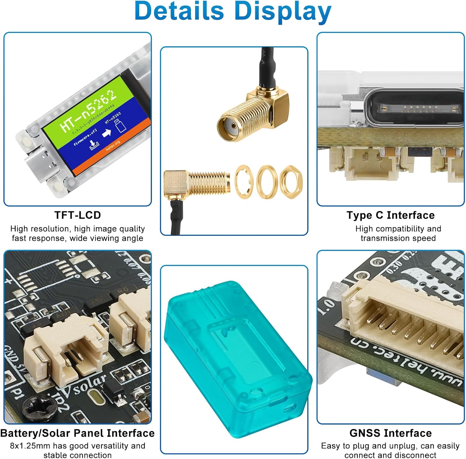
Image: Close-up view of the T114's display, USB-C port, battery/solar interface, and GNSS interface.
4. Specifications
Below are the technical specifications for the MakerHawk Mesh Node T114 Development Board V2:
| Parameter | Description |
|---|---|
| MCU | nRF52840 |
| LoRa Node Chip | SX1262 |
| Frequency | 470~510MHz; 863~870MHz; 902~928MHz |
| Max. TX Power | 21±1dBm |
| Max. Receiving Sensitivity | -135dBm@SF12 BW=125KHz |
| Bluetooth | Bluetooth LE; Bluetooth 5, Bluetooth mesh |
| Hardware Resource | USB 2.0, 4 * SPI, 2 * TWI, 2 * UART, 4 * PWM, GPSI, I2S, PDM, ODEC Etc. |
| Memory | 1M ROM, 256KB SRAM |
| Interface | Type-C USB, 2*1.25 lithium battery connector, 2*1.25 solar panel connector, LoRa ANT, 8*1.25 GPS module connector, 2*13*2.54 Header Pin |
| Battery | 3~4.2V battery power supply and charge. |
| Operating Temperature | -20 ~ 70 °C |
| Dimensions | 50.80×22.86mm |
| Electrical Characteristics | Deep Sleep: ~11uA, Tracker mode sleep: ~22uA, GPS OFF, TFT OFF: ~9mA, GPS OFF, TFT ON: ~20mA, GPS ON, TFT ON: ~51mA |
| Display | onboard 1.14 inch TFT-LCD display |
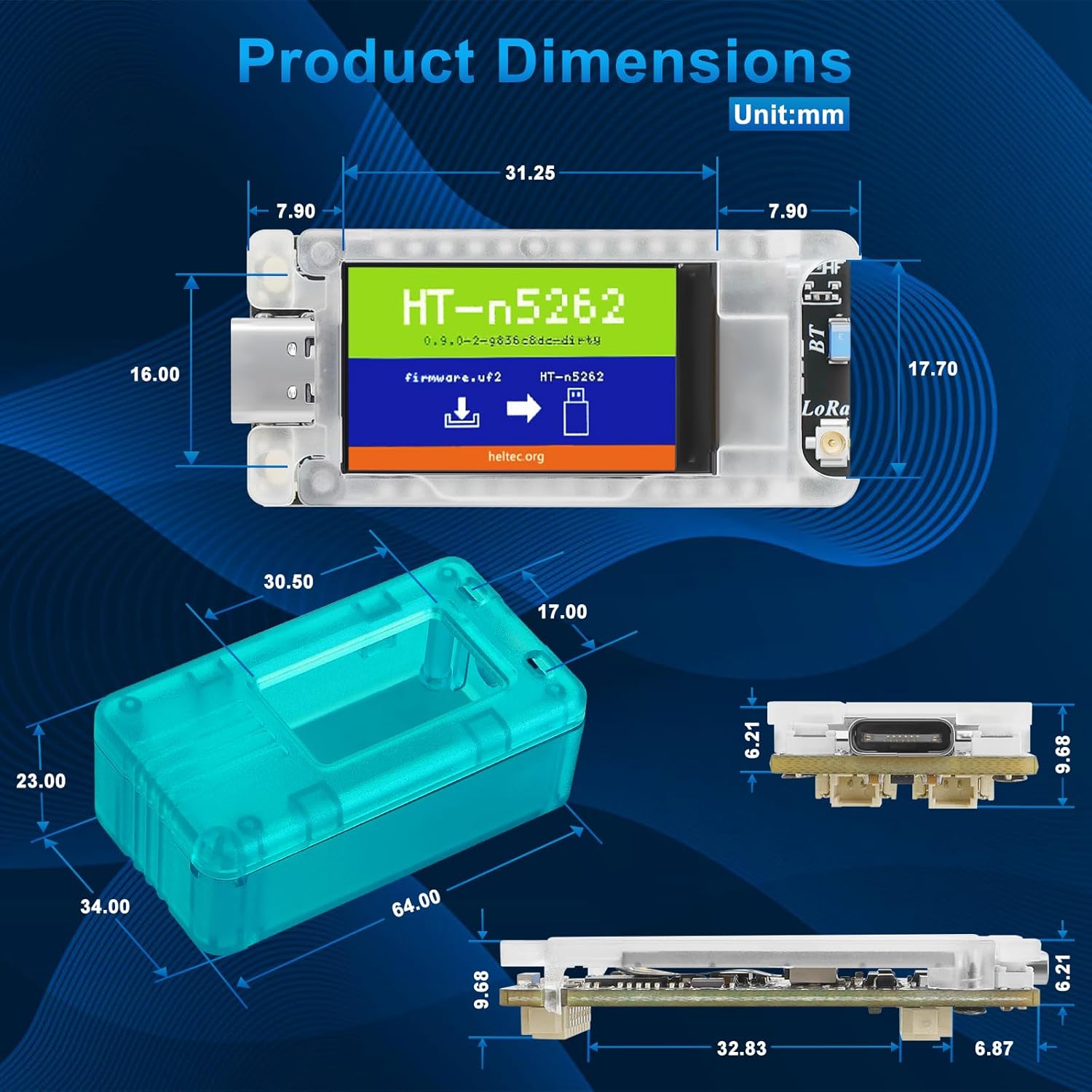
Image: Dimensional drawing of the T114 board and its protective case.

Image: GPIO Pinout diagram for the T114 board.
5. Power Options
The Mesh Node T114 offers flexible power solutions to suit various deployment scenarios:
- USB Power: The board can be powered via its 5V USB-C port, ideal for development and indoor use.
- LiPo Battery: A dedicated LiPo connector allows for portable operation with compatible lithium polymer batteries.
- Solar Panel: The integrated solar panel port enables sustainable power in outdoor and remote applications, ensuring continuous operation with minimal intervention. The board features a low-power design with an impressive standby current of just 11 µA.

Image: Power consumption comparison chart highlighting the T114's efficiency.
6. Connectivity
The T114 is equipped with multiple connection interfaces to enhance its expandability and suitability for diverse applications:
- LoRa Antenna: For long-range, low-power wireless communication.
- Bluetooth Antenna: For short-range wireless connectivity, supporting Bluetooth 5.0 and Bluetooth mesh.
- GNSS Connector: Supports external GPS modules for precise location tracking, crucial for applications in remote sensing and data tracking.

Image: Instructions for connecting an external GNSS module to the T114 board.
7. Maintenance
To ensure the longevity and optimal performance of your Mesh Node T114 Development Board, follow these maintenance guidelines:
- Cleaning: Use a soft, dry cloth to clean the board and case. Avoid using liquids or abrasive cleaners.
- Storage: Store the device in a cool, dry environment away from direct sunlight, extreme temperatures, and high humidity.
- Battery Care: If using a LiPo battery, avoid overcharging or deep discharging. Disconnect the battery if the device will be stored for an extended period.
- Firmware Updates: Regularly check for and install the latest firmware updates from the official Heltec website or Meshtastic community to benefit from performance improvements and new features.
8. Troubleshooting
If you encounter issues with your Mesh Node T114, refer to the following common troubleshooting steps:
- Device Not Powering On: Ensure the power source (USB, battery, solar) is correctly connected and providing adequate power. Check battery charge level.
- No Display Output: Verify the board is powered. If the display remains blank, try resetting the device using the Reset button.
- Communication Issues (LoRa/Bluetooth): Check antenna connections. Ensure the correct frequency band is configured in the firmware. Verify that other devices are within range and properly configured for communication.
- Firmware Upload Failure: Ensure the correct drivers are installed on your computer. Use a reliable USB-C cable. Follow the firmware flashing instructions precisely.
- GPS Not Acquiring Lock: Ensure the external GPS module is correctly connected and has a clear view of the sky. Allow sufficient time for initial satellite acquisition.
For more detailed troubleshooting or specific firmware-related issues, consult the official Heltec documentation or the Meshtastic community forums.
9. Warranty and Support
MakerHawk products are designed for reliability and performance. For any product-related inquiries or support, please refer to the following:
- Manufacturer: MakerHawk
- Return Policy: This product is subject to a 30-day return policy for refunds or replacements.
- Online Resources: For additional documentation, schematics, datasheets, and community support, visit the official Heltec website or the MakerHawk store: MakerHawk Store on Amazon.

Image: Screenshot of the Heltec Automation documentation and resources page.


