
1. Introduction
The GOTOTOP STC-1000 is a versatile digital temperature controller designed for precise temperature management in various applications, including homebrewing, fermentation, and other environments requiring controlled heating and cooling. This device features automatic mode conversion between heating and cooling, a wide temperature control range, and audible/visual alarm functions for high temperature and sensor failure. This manual provides detailed instructions for installation, operation, and maintenance to ensure optimal performance and longevity of your device.
2. Product Overview
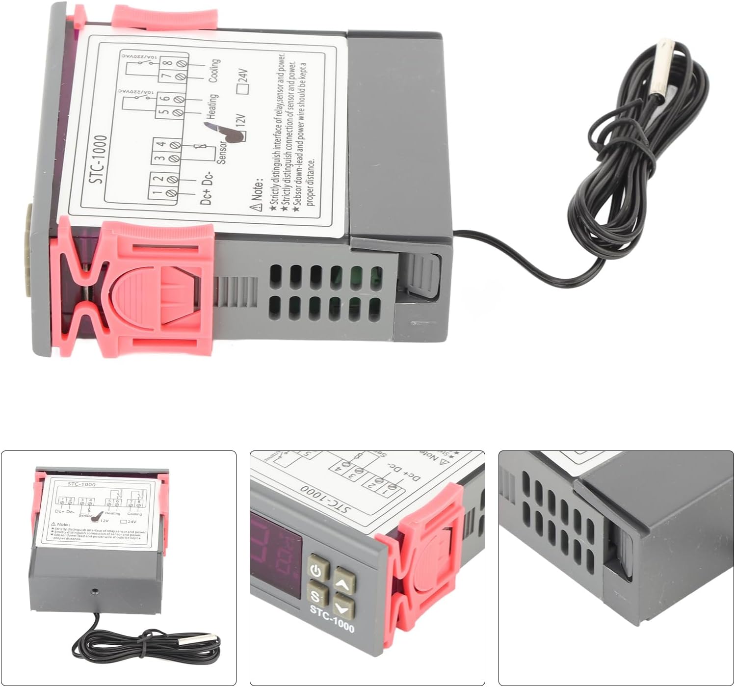
The STC-1000 temperature controller is equipped with a clear digital display for current temperature readings and settings. It features intuitive buttons for setting parameters and switching modes. The device is housed in a flame-retardant ABS material shell for durability and safety. It includes a temperature sensor with a 1-meter cable for accurate measurement.

Figure 2.1: Front view of the GOTOTOP STC-1000 Digital Temperature Controller, showing the display and control buttons.
3. Specifications
| Feature | Specification |
|---|---|
| Model | STC-1000 |
| Shell Material | ABS flame retardant plastic |
| Measuring & Control Temperature Range | -50℃ to 110℃ (-58°F to 230°F) |
| Resolution | 0.1℃ |
| Accuracy | ±1℃ |
| Relay Output Capacity | 10A/240VAC (for 12V model, this refers to the relay rating; actual output depends on input voltage) |
| Sensor Type | NTC sensor, cable length approx. 1 meter (3.3ft) |
| Power Supply | 12V DC (Specific to this model) |
| Item Weight | 4.6 ounces |
| Package Dimensions | 3.94 x 3.15 x 1.18 inches |
4. Setup and Wiring
Proper wiring is critical for the safe and correct operation of the STC-1000. Refer to the wiring diagram below and follow these instructions carefully. Ensure all power is disconnected before attempting any wiring.

Figure 4.1: Wiring diagram for the STC-1000. Note the distinction between power input, sensor, heating, and cooling connections.
Wiring Connections:
- Power Input (DC+ / DC-): Connect your 12V DC power supply to terminals 1 and 2. Terminal 1 is DC+, Terminal 2 is DC-. Ensure correct polarity.
- Temperature Sensor: Connect the NTC temperature sensor to terminals 3 and 4. The sensor is non-polar, so connection order does not matter.
- Heating Output: Connect your heating device (e.g., heating pad, heater) to terminals 5 and 6. These are relay contacts. The STC-1000 will switch power to your heating device through these terminals.
- Cooling Output: Connect your cooling device (e.g., cooling fan, refrigerator compressor) to terminals 7 and 8. These are also relay contacts. The STC-1000 will switch power to your cooling device through these terminals.
Important Note: Strictly distinguish between the interface of the relay/sensor and power. Strictly distinguish between the connections of the sensor and power. The sensor lead and power wire should be kept a proper distance apart to avoid interference.
5. Operating Instructions
The STC-1000 features a simple interface for setting temperature and operating modes.
5.1. Power On/Off
- Press and hold the Power button (
 ) for 3 seconds to turn the device ON or OFF.
5.2. Setting Temperature Parameters
To set the desired temperature range, you need to adjust two main parameters: the Set Point (SP) and the Differential Temperature (DIF).
- Accessing Settings: Press the 'S' button (Set) for 3 seconds to enter the parameter setting mode. The display will show "F1".
- Navigating Parameters: Use the Up () and Down () arrow buttons to cycle through the parameters (F1, F2, F3, F4).
- Adjusting Parameter Values:
- F1 (Set Point - SP): This is your desired target temperature. Press 'S' once when F1 is displayed, then use Up/Down to adjust the value. Press 'S' again to confirm.
- F2 (Differential Temperature - DIF): This is the hysteresis, or the difference between the set point and the temperature at which the heating/cooling will turn off. For example, if SP is 25°C and DIF is 2°C:
- In cooling mode: Cooling turns on at >25°C, turns off at 23°C.
- In heating mode: Heating turns on at <25°C, turns off at 27°C.
- F3 (Compressor Delay - CPT): This sets a delay time (in minutes) for the compressor (cooling device) to restart after being turned off. This protects the compressor from short cycling. Adjust F3 similarly to F1.
- F4 (Temperature Calibration - CAL): Allows for fine-tuning the temperature reading if there's a discrepancy with a known accurate thermometer. Adjust F4 similarly to F1.
- Exiting Settings: After adjusting parameters, press and hold the Power button or wait for 10 seconds for the device to automatically exit the setting mode and save changes.
5.3. Cooling and Heating Mode Conversion
The STC-1000 automatically switches between cooling and heating modes based on the set point (F1) and the differential temperature (F2).
- If the current temperature is higher than F1 + F2, the cooling relay will activate.
- If the current temperature is lower than F1 - F2, the heating relay will activate.
- The "Cool" and "Heat" indicators on the display will illuminate accordingly.
5.4. Alarm Functions
The device includes audible and visual alarms for specific conditions:
- High Temperature Alarm: If the temperature exceeds a certain threshold (often related to F1 + F2, or a separate high-temperature alarm setting if available, which is not explicitly listed in the provided data but common for STC-1000 models), an alarm will sound.
- Sensor Failure Alarm: If the temperature sensor is disconnected or faulty, the display will show "EE" and an alarm will sound.
6. Maintenance
To ensure the longevity and accurate operation of your STC-1000 temperature controller, follow these maintenance guidelines:
- Cleaning: Wipe the device with a soft, dry cloth. Do not use abrasive cleaners or solvents. Ensure no liquids enter the device.
- Sensor Care: Keep the temperature sensor clean and free from debris. Avoid bending or damaging the sensor cable.
- Environmental Conditions: Operate the controller within its specified temperature and humidity ranges. Avoid exposure to direct sunlight, excessive moisture, or corrosive environments.
- Wiring Inspection: Periodically check all wiring connections to ensure they are secure and free from corrosion or damage.
7. Troubleshooting
If you encounter issues with your STC-1000, refer to the following common problems and solutions:
| Problem | Possible Cause | Solution |
|---|---|---|
| Display shows "EE" | Sensor error or disconnected sensor. | Check the sensor connection to terminals 3 and 4. Ensure the sensor cable is not damaged. Replace the sensor if faulty. |
| Display shows "HHH" or "LLL" | Temperature exceeds or falls below the measurable range. | Ensure the ambient temperature is within the -50℃ to 110℃ range. Check sensor placement. |
| Heating/Cooling device not activating |
|
|
| Inaccurate temperature reading |
|
|
8. Warranty and Support
Specific warranty information for this product is not provided in the available documentation. For warranty claims or technical support, please contact your retailer or the manufacturer, GOTOTOP, directly. Keep your purchase receipt as proof of purchase.
For further assistance, you may visit the GOTOTOP Store on Amazon.