Introduction
This manual provides essential information for the safe and efficient operation of your Cantonape 3000W Power Inverter. This device converts 12V DC power from a battery into 110V/120V AC power, suitable for various applications including vehicles, outdoor activities, and off-grid systems. Please read these instructions thoroughly before installation and use.
Safety Information
Observe the following safety precautions to prevent injury or damage to the inverter and connected devices:
- Ensure proper ventilation around the inverter. Do not block cooling vents.
- Keep the inverter away from water, moisture, and flammable materials.
- Connect the inverter only to a 12V DC power source. Connecting to a 24V or higher DC source will damage the unit.
- Always connect the inverter to the battery terminals with correct polarity (positive to positive, negative to negative). Reverse polarity will cause damage.
- Do not exceed the continuous output power of 3000W. The inverter has a peak power capacity of 6000W for short durations.
- Ensure all connections are secure and properly insulated to prevent short circuits.
- In case of an abnormal state, the inverter will display an error code and may shut down. Refer to the Troubleshooting section.
- The inverter generates heat during operation. Avoid touching the casing directly during heavy loads.
Product Overview
Inverter Components
The Cantonape 3000W Power Inverter features multiple input and output ports, along with essential controls and indicators.

Image: Inverter Front and Rear Panels. This image displays the inverter's front panel with four AC output sockets, four USB 5V output ports, an ON/OFF switch, and an earth wire terminal. The rear panel shows the positive (red) and negative (black) DC 12V input terminals, along with two cooling fans.
Intelligent LCD Display
The integrated LCD provides real-time operational status and diagnostic information.
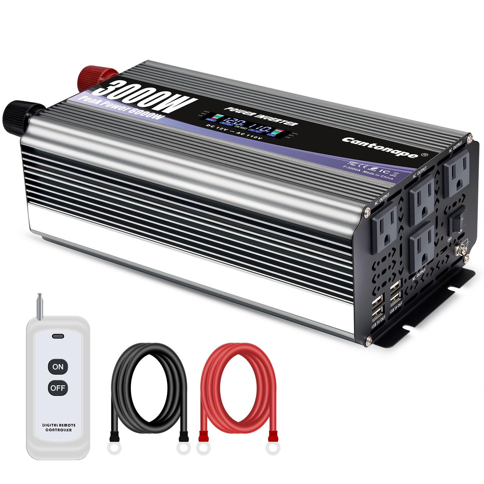
Image: LCD Display Details. The LCD display shows five key indicators: 1. Battery Capacity, 2. Battery Voltage, 3. Output Frequency, 4. Output Voltage, and 5. Load Capacity. This allows for monitoring of the inverter's performance and power source status.
In normal operation, the LCD displays input/output voltage, battery capacity, load capacity, and output frequency. In case of an abnormal condition, an error code will be displayed. Refer to the Troubleshooting section for details on error codes.
Safety Protection Features
The inverter incorporates multiple protection mechanisms to ensure safe operation for both the device and connected appliances.
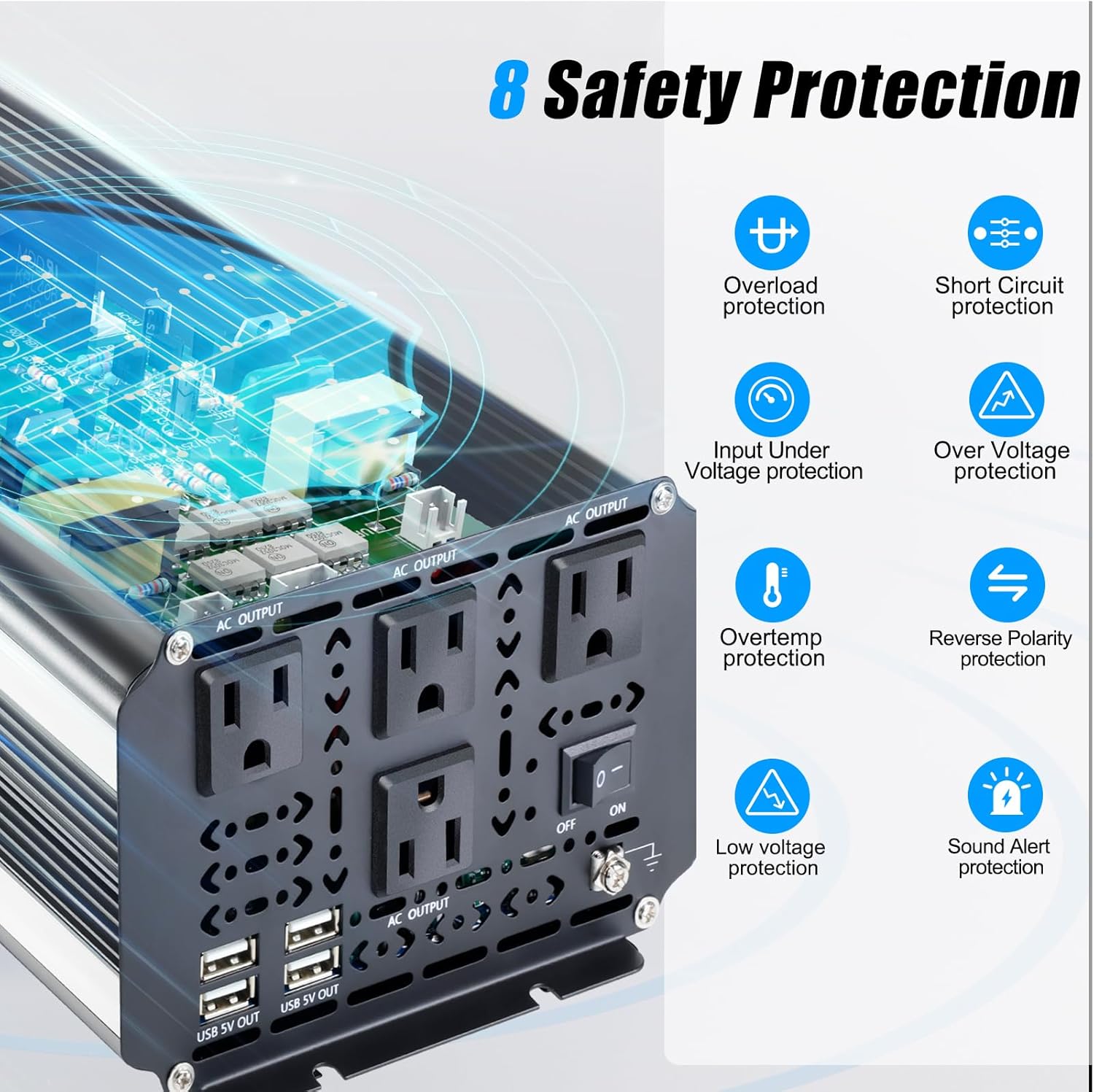
Image: 8 Safety Protection Features. This graphic highlights the inverter's comprehensive safety features, including protection against overload, short circuit, input under-voltage, over-voltage, over-temperature, reverse polarity, low voltage, and a sound alert system.
Setup
Connecting the Inverter to a 12V Battery
- Ensure the inverter's ON/OFF switch is in the 'OFF' position.
- Connect the red battery cable to the positive (+) terminal of the 12V battery.
- Connect the other end of the red battery cable to the positive (red) terminal on the inverter.
- Connect the black battery cable to the negative (-) terminal of the 12V battery.
- Connect the other end of the black battery cable to the negative (black) terminal on the inverter.
- Securely tighten all connections. Loose connections can cause overheating and damage.
- Connect the earth wire from the inverter's earth terminal to a suitable ground point (e.g., vehicle chassis or dedicated ground rod).
Remote Controller Setup
The remote controller allows for convenient power control. It requires a 12V 23A battery (not included). Insert the battery into the remote controller according to the polarity markings. The remote control operates wirelessly, with an effective range of approximately 160 feet without obstruction.

Image: Wireless Remote Control. This image illustrates the use of the wireless remote control for the inverter, highlighting its convenience for outdoor or remote setups.
Solar System Integration (Example)
The inverter can be integrated into a solar power system. Below is a typical connection diagram.

Image: Solar System Connection Diagram. This diagram illustrates how the inverter fits into a solar power setup, connecting to a 12V battery charged by solar panels via a charge controller, providing both DC and AC power outputs.
Operating Instructions
Powering On/Off
- After ensuring all connections are secure, switch the inverter's ON/OFF switch to the 'ON' position.
- The LCD display will illuminate, showing the current battery voltage and other parameters.
- To turn off the inverter, switch the ON/OFF switch to the 'OFF' position.
- Alternatively, use the remote controller to turn the inverter on or off.
Connecting AC and USB Devices
- Plug your AC appliances into the 110V/120V AC outlets on the inverter.
- Plug your USB-powered devices into the 5V USB ports.
- Monitor the LCD display for load capacity to ensure you do not exceed the inverter's continuous power rating of 3000W.
- For devices with high startup current (e.g., motors, compressors), the inverter's 6000W peak power can handle the initial surge, but ensure the continuous running wattage is within 3000W.
Maintenance
Regular maintenance ensures optimal performance and longevity of your inverter.
- Cleaning: Periodically clean the inverter's exterior, especially the cooling fan vents, to prevent dust buildup. Use a dry, soft cloth. Do not use liquid cleaners.
- Connection Check: Regularly inspect battery cables and other connections for tightness and corrosion. Loose connections can lead to power loss and overheating.
- Storage: If storing the inverter for an extended period, disconnect it from the battery and store it in a cool, dry place.

Image: Efficient Cooling Fan. The inverter features temperature-controlled cooling fans that activate automatically to prevent overheating and maintain optimal operating temperature.
Troubleshooting
The intelligent LCD display will show error codes if an issue occurs. Refer to the table below for common error codes and their solutions.

Image: Powerful Display and Error Codes. This image shows the inverter's LCD displaying an error code (E-1) and lists various error codes with their corresponding protection types, aiding in quick troubleshooting.
| Error Code | Description | Possible Solution |
|---|---|---|
| E-1 | Low Voltage Protection | Recharge or replace the 12V battery. Check battery connections. |
| E-2 | High Voltage Protection | Verify the input voltage is within the 12V specification. Disconnect from over-voltage source. |
| E-3 | Overtemperature Protection | Reduce load. Ensure proper ventilation and clear cooling fan vents. Allow inverter to cool down. |
| E-4 | Overload Protection | Reduce the total wattage of connected appliances. Ensure total load does not exceed 3000W continuous. |
| E-5 | Short Circuit Protection | Disconnect all AC and USB loads. Check for short circuits in connected devices or wiring. |
| E-6 | Repeated Faults Shutdown, Restart Required | Turn off the inverter, wait a few minutes, and then restart. If the error persists, check for underlying issues. |
| E-7 | Repeated Low Voltage | Similar to E-1, indicates persistent low battery voltage. Recharge or replace battery. |
If the issue persists after attempting these solutions, please contact customer support.
Specifications
| Feature | Specification |
|---|---|
| Model Name | MSW3000W |
| Continuous Output Power | 3000 Watts |
| Peak Output Power | 6000 Watts |
| Input Voltage | DC 12V |
| Output Voltage | AC 110V/120V |
| Output Frequency | 60Hz |
| AC Outlets | 4 |
| USB Ports | 4 x 5V |
| Product Dimensions | 11.93 x 6.34 x 4.06 inches |
| Item Weight | 7.15 pounds |
| Power Source | Battery Powered |

Image: Inverter Dimensions. This image provides a visual representation of the inverter's physical dimensions, useful for installation planning.
Warranty and Support
The Cantonape 3000W Power Inverter comes with a 12-Months Warranty from the date of purchase, covering manufacturing defects.
Cantonape is committed to providing reliable and trustworthy after-sales service. For technical support, warranty claims, or any inquiries regarding your product, please visit the official Cantonape Store or contact their customer service.
Cantonape Store: Visit Cantonape Store on Amazon