
1. Introduction
This manual provides detailed instructions for the safe and effective use of the MASTECH MAS830B Digital Multimeter. The MAS830B is a compact, battery-powered handheld device designed for measuring DC and AC voltage, DC current, resistance, diode, and continuity. It features a 2000-count display and a low battery indicator.
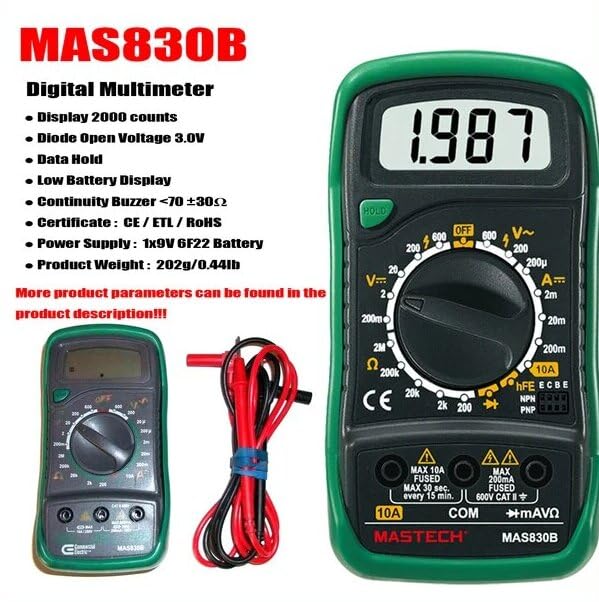
Figure 1: MASTECH MAS830B Digital Multimeter. This image displays the front view of the multimeter, highlighting its 2000-count display, rotary switch for function selection, input jacks, and key features such as Data Hold and Low Battery Display.
2. Safety Information
To ensure safe operation and service of the meter, follow these safety precautions:
- Always ensure the meter is in good working condition before use.
- Do not apply voltage or current that exceeds the maximum specified limits.
- Use caution when working with voltages above 30V AC RMS, 42V peak, or 60V DC. These voltages pose a shock hazard.
- Always disconnect the test leads from the circuit before changing functions.
- Replace the battery immediately when the low battery indicator appears to ensure accurate readings.
- Do not operate the meter if the battery cover is not properly closed.
- Adhere to local and national safety codes.
3. Product Features
The MASTECH MAS830B Digital Multimeter includes the following key features:
- Display: 2000 counts for precise readings.
- Diode Open Voltage: 3.0V for diode testing.
- Data Hold: Freezes the displayed reading for convenience.
- Low Battery Display: Indicates when the battery needs replacement.
- Continuity Buzzer: Sounds when resistance is less than 70 ±30Ω.
- Certifications: CE / ETL / RoHS compliant.

Figure 2: Detailed features and general specifications of the MASTECH MAS830B. This image provides a clear list of the multimeter's capabilities and general characteristics, including power supply, product size, weight, and certifications.
4. Components Included
The product package typically includes:
- 1 x MASTECH MAS830B Digital Multimeter
- 1 x Pair of Test Leads
- 1 x User's Manual

Figure 3: Packaging contents and main applications of the MAS830B. This image illustrates what is included in the box, such as the multimeter, test leads, and quick start guide, along with common applications in domestic and electronics settings.
5. Setup
5.1. Battery Installation
- Ensure the multimeter is turned OFF.
- Locate the battery compartment cover on the back of the unit.
- Unscrew the retaining screw(s) and remove the cover.
- Insert a new 9V 6F22 battery, observing the correct polarity.
- Replace the battery cover and secure it with the screw(s).
5.2. Connecting Test Leads
- Insert the black test lead into the COM (common) jack.
- For most measurements (voltage, resistance, diode, continuity, and current up to 200mA), insert the red test lead into the VΩmA jack.
- For high current measurements (up to 10A), insert the red test lead into the 10A jack. Ensure the rotary switch is set to the appropriate 10A range.
6. Operating Instructions
To operate the multimeter, select the desired function using the rotary switch.
6.1. Measuring DC Voltage (V=)
- Set the rotary switch to the desired DC Voltage (V=) range (e.g., 20V, 200V).
- Connect the red test lead to the positive (+) side of the circuit and the black test lead to the negative (-) side.
- Read the voltage value on the display.
6.2. Measuring AC Voltage (V~)
- Set the rotary switch to the desired AC Voltage (V~) range (e.g., 200V, 600V).
- Connect the test leads across the AC voltage source.
- Read the voltage value on the display.
6.3. Measuring DC Current (A=)
- Set the rotary switch to the desired DC Current (A=) range (e.g., 200mA, 10A).
- Important: For currents up to 200mA, use the VΩmA jack. For currents up to 10A, use the 10A jack.
- Disconnect power to the circuit. Open the circuit where current is to be measured.
- Connect the multimeter in series with the circuit, ensuring the red lead is towards the higher potential and the black lead towards the lower potential.
- Apply power to the circuit and read the current value.
6.4. Measuring Resistance (Ω)
- Set the rotary switch to the desired Resistance (Ω) range.
- Ensure the circuit is de-energized before measuring resistance.
- Connect the test leads across the component to be measured.
- Read the resistance value on the display.
6.5. Diode Test
- Set the rotary switch to the Diode symbol (→|).
- Connect the red test lead to the anode and the black test lead to the cathode of the diode.
- The display will show the forward voltage drop. Reverse the leads; the display should show 'OL' (Open Loop) for a good diode.
6.6. Continuity Test
- Set the rotary switch to the Continuity symbol ()))).
- Connect the test leads across the circuit or component.
- If the resistance is below approximately 70 ±30Ω, the buzzer will sound, indicating continuity.
6.7. Data Hold Function
- During any measurement, press the 'HOLD' button to freeze the current reading on the display.
- Press the 'HOLD' button again to release the reading and resume live measurements.
7. Maintenance
7.1. Battery Replacement
When the low battery indicator appears on the display, replace the 9V 6F22 battery as described in the 'Battery Installation' section (5.1).
7.2. Cleaning
Wipe the case with a damp cloth and mild detergent. Do not use abrasives or solvents. Keep the input terminals free from dirt and moisture.
8. Troubleshooting
- No display or erratic readings: Check battery charge and ensure proper installation.
- 'OL' (Overload) displayed: The measured value exceeds the selected range. Select a higher range or ensure the circuit is within the meter's capabilities.
- Incorrect readings: Verify test lead connections, ensure the correct function and range are selected, and check for a low battery.
- No continuity beep: Ensure the circuit resistance is below 70 ±30Ω.
9. Specifications
| Measurement | Range | Resolution | Accuracy |
|---|---|---|---|
| DC Voltage | 200mV, 2V, 20V, 200V, 600V | 0.1mV to 1V | ±(0.5%+3) to ±(0.8%+5) |
| AC Voltage | 200V, 600V | 0.1V to 1V | ±(1.2%+10) |
| DC Current | 200µA, 2mA, 20mA, 200mA, 10A | 0.1µA to 10mA | ±(1.0%+3) to ±(3.0%+10) |
| Resistance | 200Ω, 2kΩ, 20kΩ, 200kΩ, 2MΩ | 0.1Ω to 1kΩ | ±(0.8%+5) to ±(1.0%+5) |
| Diode Open Voltage | 3.0V | ||
| Continuity Buzzer | <70 ±30Ω | ||
| Display | 2000 counts | ||
| Power Supply | 1 x 9V 6F22 Battery | ||
| Product Dimensions (L x W x H) | 145mm x 76mm x 40mm (5.7" x 3" x 1.57") | ||
| Product Weight | 202g (0.44lb) | ||
| Certifications | CE, ETL, RoHS | ||
| Operating Temperature | 0°C to 50°C | ||
10. Warranty and Support
This product is covered by a standard manufacturer's warranty. For specific warranty terms, technical support, or service inquiries, please refer to the documentation provided with your purchase or contact the retailer/manufacturer directly. Spare parts availability in the EU is typically 1 year.


