1. Introduction
The FNRSI DSO-510 is an upgraded 2-in-1 digital portable oscilloscope and DDS signal generator designed for a wide range of applications, from automotive diagnostics to general electronics testing. This compact device offers enhanced functionalities over previous models, providing a 10MHz bandwidth and a 48MS/s sampling rate. It is equipped with a 2.8-inch TFT display for clear waveform visualization and intuitive operation.
Its integrated DDS signal generator can output 13 different waveforms, making it a versatile tool for both periodic analog and non-periodic digital signal analysis. The DSO-510 features a built-in 1000mAH rechargeable Li-ion battery, ensuring portability and up to 4 hours of continuous operation.

Figure 1.1: FNRSI DSO-510 Oscilloscope with its standard accessories, including the 10X probe, signal generator cables, and USB charging cable.
2. Package Contents
Please verify that all items listed below are included in your package. If any items are missing or damaged, please contact customer support.
- FNRSI DSO-510 Digital Portable Oscilloscope / DDS Signal Generator Unit
- 10X Oscilloscope Probe
- Signal Generator Output Cable (with alligator clips)
- USB Type-C Charging Cable
- User Manual (this document)
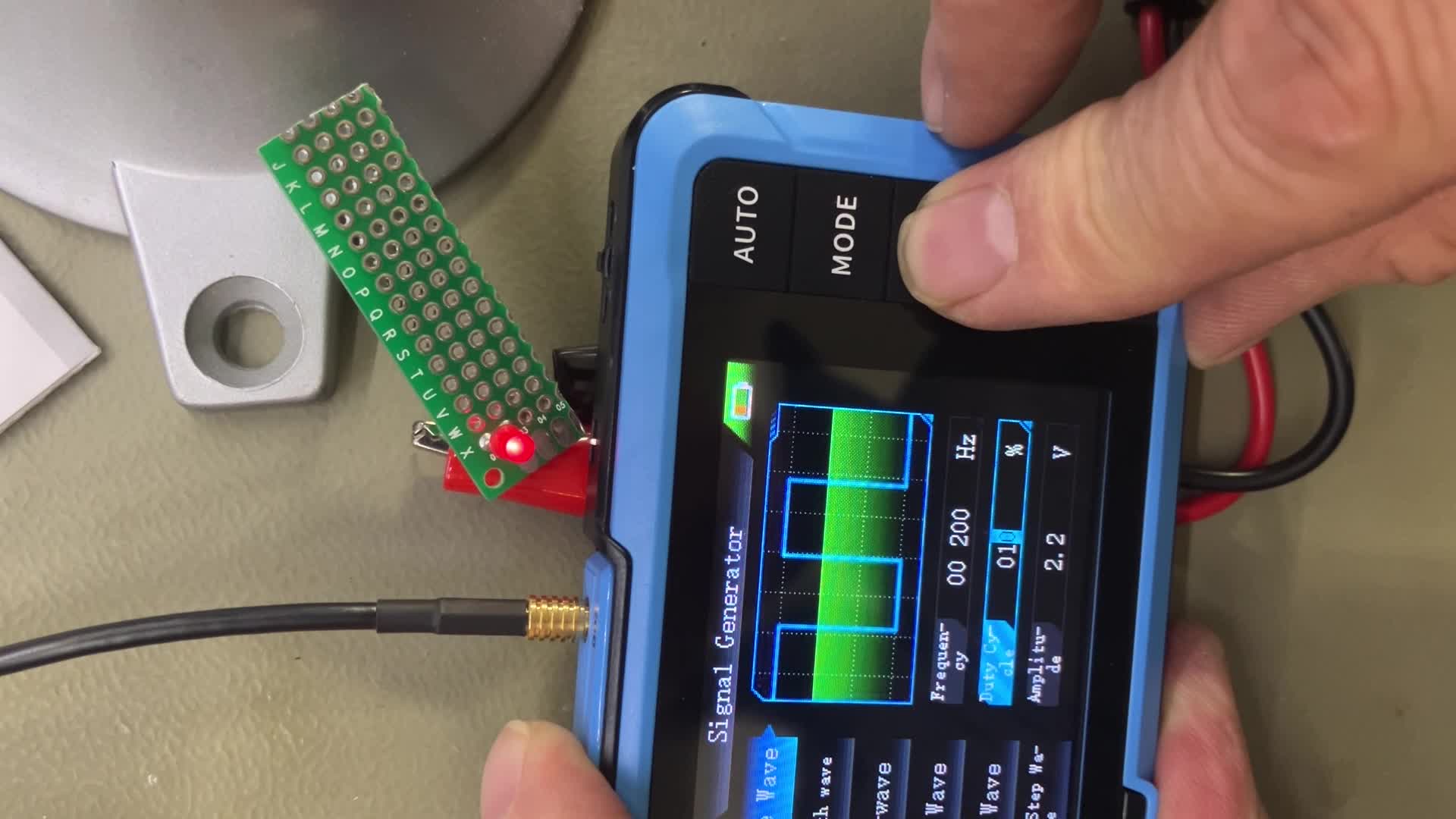
Figure 2.1: An overhead view of the FNRSI DSO-510 and its accessories laid out, including the main unit, oscilloscope probe, signal generator cables, USB cable, and the instruction manual.
3. Setup and Initial Use
3.1 Charging the Device
The DSO-510 comes with a built-in 1000mAH rechargeable Li-ion battery. For optimal performance and battery longevity, fully charge the device before its first use.
- Connect the USB Type-C charging cable to the device's Type-C port (located on the side).
- Connect the other end of the USB cable to a 5V/1A USB power adapter (not included) or a computer USB port.
- The charging indicator light will illuminate during charging and turn off when fully charged. A full charge typically takes approximately 2 hours.

Figure 3.1: The device display indicating battery charge status and the internal battery graphic, highlighting its power reserve capabilities.
3.2 Powering On/Off
To power on the device, long press the Power button located on the side. To power off, long press the Power button again.
3.3 Language Selection
Upon first power-on, the device may default to Chinese. To change the language to English:
- Long press the MODE button to enter the main menu.
- Use the Up/Down arrow buttons to navigate to the Settings icon (often represented by a gear or wrench symbol).
- Short press the RUN button to confirm selection.
- Navigate to Language and select English using the arrow buttons and RUN button to confirm.
4. Operation
4.1 Button Functions
The DSO-510 features a user-friendly interface with dedicated buttons for various functions:

Figure 4.1: A detailed diagram illustrating the layout and functions of the buttons on the FNRSI DSO-510, along with a table of oscilloscope and signal generator parameters.
- AUTO Button: Short press for automatic parameter setting; long press for baseline calibration.
- MODE Button: Short press to switch between Oscilloscope and Signal Generator modes; long press to enter/exit main menu.
- Up/Down Arrow Buttons: Navigate menus, adjust parameters.
- Left/Right Wheel Button: Adjust horizontal time base (left/right) or vertical sensitivity (up/down).
- RUN Button: Short press to start/stop waveform acquisition; long press to save waveform image.
4.2 Oscilloscope Mode
In Oscilloscope mode, the device displays real-time waveforms, allowing for detailed analysis of electrical signals.
- Connecting the Probe: Connect the 10X oscilloscope probe to the BNC connector on the top of the device. Ensure the probe's attenuation switch is set correctly (e.g., 1X or 10X) to match the device's settings for accurate readings.
- Auto-Setting: Press the AUTO button for quick automatic adjustment of vertical scale, horizontal time base, and trigger level to display a stable waveform.
- Manual Adjustments: Use the wheel button to fine-tune the horizontal time base and vertical sensitivity. Use the arrow buttons to adjust the trigger level.
- Trigger Modes: The device supports Auto, Normal, and Single trigger modes. Select the appropriate mode based on the signal characteristics.
- Waveform Analysis: The device supports waveform pause, zoom, and movement for detailed inspection of signals, including hidden noise or complex modulation patterns.

Figure 4.2: The FNRSI DSO-510 showcasing its 2-in-1 functionality, displaying an oscilloscope waveform, a DDS signal generator interface, and the infinite afterglow feature.

Figure 4.3: User interacting with the DSO-510 to analyze a waveform, highlighting the device's support for waveform pause, zoom, and movement for detailed insights.
4.3 Signal Generator Mode (DDS)
The integrated DDS signal generator can output various waveforms for testing and calibration purposes.
- Switching Modes: Short press the MODE button to switch to Signal Generator mode.
- Waveform Selection: Use the Up/Down arrow buttons to select from 13 different waveforms, including sine, square, triangle, full-wave, half-wave, noise, and DC.
- Parameter Adjustment: Adjust frequency (up to 50KHz), duty cycle (0-100%), and amplitude (0.1-3.3V) using the arrow buttons and wheel button.
- Output Connection: Connect the signal generator output cable to the dedicated port and use the alligator clips to connect to your circuit.
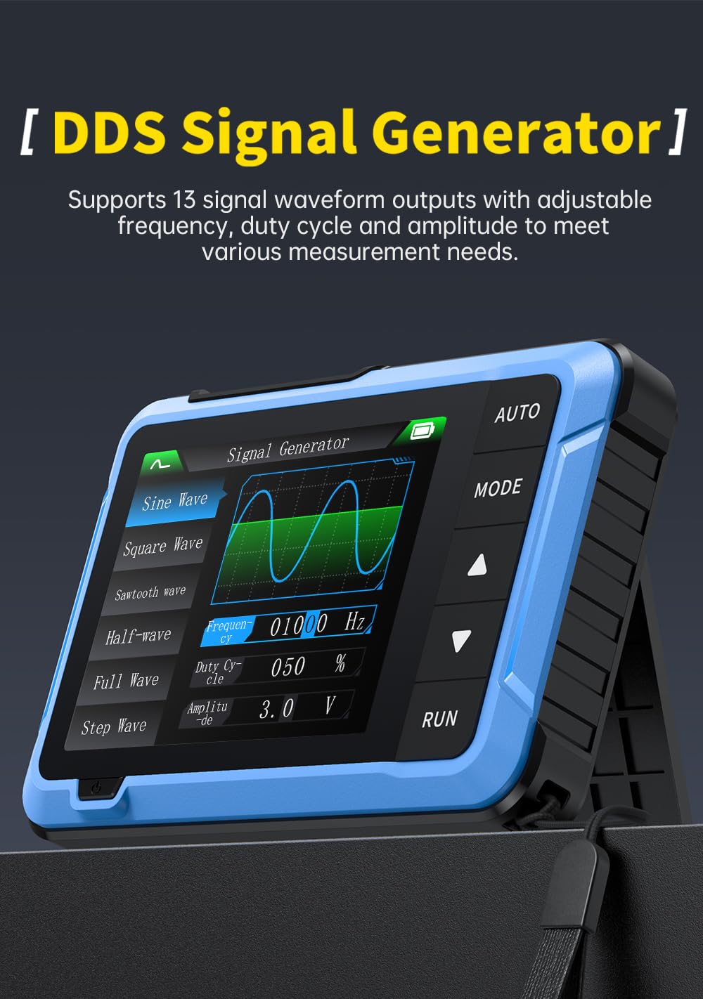
Figure 4.4: The DSO-510 in Signal Generator mode, showing options for selecting waveform types and adjusting frequency, duty cycle, and amplitude.
4.4 Measurement Examples
The DSO-510 is capable of various waveform measurements:

Figure 4.5: Examples of different waveform measurements, including 220V mains voltage detection, pulse signal detection, power supply ripple detection, and other general waveform measurements.
- 220V Mains Voltage Detection: Capable of safely measuring high voltages up to 400V with the 10X probe.
- Pulse Signals Detection: Ideal for analyzing digital signals and pulse trains.
- Power Supply Ripple Detection: Useful for checking the stability and quality of power supplies.
- Other Waveform Measurements: Versatile for a wide range of electronic signals.
5. Maintenance
5.1 Battery Care
To maximize battery life and performance:
- Avoid fully discharging the battery frequently.
- Store the device with a partial charge (around 50%) if not used for extended periods.
- Recharge the device at least once every three months to prevent deep discharge.
- Do not charge the device in extreme temperatures.
5.2 Cleaning
Clean the device regularly to ensure proper function and longevity:
- Use a soft, dry cloth to wipe the exterior of the device.
- For stubborn dirt, slightly dampen the cloth with water or a mild, non-abrasive cleaner.
- Do not use harsh chemicals, solvents, or abrasive materials, as these can damage the device's casing and screen.
- Ensure the device is powered off and disconnected from any power source before cleaning.
5.3 Firmware Update
Firmware updates may be released to improve performance or add new features. Refer to the official FNRSI website for the latest firmware and instructions. Typically, updates involve connecting the device to a computer via the Type-C USB port and following specific software prompts.
6. Troubleshooting
| Problem | Possible Cause | Solution |
|---|---|---|
| Device does not power on. | Low or depleted battery. | Connect the device to a power source using the USB Type-C cable and charge it fully. |
| No waveform displayed in Oscilloscope mode. | Probe not connected correctly; incorrect trigger settings; signal too weak or out of range. | Ensure the probe is securely connected. Press AUTO button. Adjust vertical sensitivity and trigger level. Check signal source. |
| Waveform is unstable or noisy. | Improper grounding; external interference; incorrect time base or trigger settings. | Ensure proper grounding. Minimize external interference. Adjust time base and trigger settings. |
| Signal generator output is incorrect. | Incorrect waveform, frequency, or amplitude settings. | Verify the selected waveform type and adjust frequency, duty cycle, and amplitude parameters. |
| Screen is unresponsive or frozen. | Software glitch. | Perform a soft reset by long pressing the power button until the device turns off, then restart. If issue persists, locate the reset hole (small pinhole) and gently press with a thin object. |
7. Technical Specifications
7.1 Oscilloscope Parameters
- Sampling Rate: 48MS/s
- Bandwidth: 10MHz
- Vertical Sensitivity: 10mV/Div - 10V/Div
- Time Base Range: 50ns-20S
- Voltage Range: X1: ±40V (Vpp:80V), X10: ±400V (Vpp:800V)
- Trigger Mode: Automatic/Normal/Single
- Trigger Edge: Rising edge / Falling edge
- Coupling: AC/DC
- 1KHz Calibration Square Wave: Frequency: 1KHz, Duty Cycle: 50%, Amplitude: 3.3V
7.2 Signal Generator Parameters
- Frequency: 0-50KHz
- Duty Cycle: 0-100% (for rectangular and sawtooth wave)
- Amplitude: 0.1-3.3V
- Waveforms: Sine wave, rectangular wave, sawtooth wave, half wave, full wave, step wave, reverse step wave, noise, DC, exponential rise, exponential drop, DC signal, multi-tone, Sink pulse, Lorentz wave (13 types total)
7.3 General Parameters
- Display: 2.8 inch TFT, 320*240 resolution
- USB Charging: 5V/1A
- Battery Capacity: 1000mAH
- Size: 99 x 68.3 x 19.5 mm
- Weight: Approximately 10.23 ounces (290g)
8. Warranty and Support
This FNRSI product is covered by a standard manufacturer's warranty against defects in materials and workmanship. Please refer to the product packaging or the official FNRSI website for specific warranty terms and conditions.
For technical support, troubleshooting assistance, or warranty claims, please contact FNRSI customer service through the contact information provided on the official product page or your retailer's website. Please have your product model and purchase date ready when contacting support.
We are committed to providing high-quality products and excellent customer service. Your feedback is valuable to us.