1. Introduction
The MESTEK CBF01 is a dual-purpose electrical tool designed to accurately and quickly identify the correct circuit breaker or fuse for a specific electrical outlet, and to test GFCI (Ground Fault Circuit Interrupter) outlets for proper wiring and functionality. This device enhances safety and efficiency for electrical work by simplifying the process of locating circuits and verifying outlet integrity.
2. Safety Information
Always observe basic safety precautions when using electrical testing equipment to reduce the risk of fire, electric shock, and personal injury.
- Read all instructions before use.
- Do not use the device if it appears damaged or is not operating correctly.
- Ensure the operating voltage (AC 90V~135V) and frequency (50Hz~60Hz) are within the specified range for your electrical system.
- Wear appropriate personal protective equipment, such as insulated gloves and safety glasses, when working with electrical circuits.
- This device is intended for use on North American 3-wire 120V electrical outlets only.
- Never attempt to open or modify the device. There are no user-serviceable parts inside.
- Keep the device away from water and moisture.
3. Package Contents
Verify that all items are present in the package:
- MESTEK CBF01 Circuit Breaker Finder Receiver
- MESTEK CBF01 GFCI Outlet Tester (Transmitter)
- 2 x AAA Batteries (for Receiver)
- User Manual
- Carrying Pouch
- Small Screwdriver

4. Product Overview
The MESTEK CBF01 consists of two main components: the Receiver and the Transmitter (GFCI Outlet Tester).
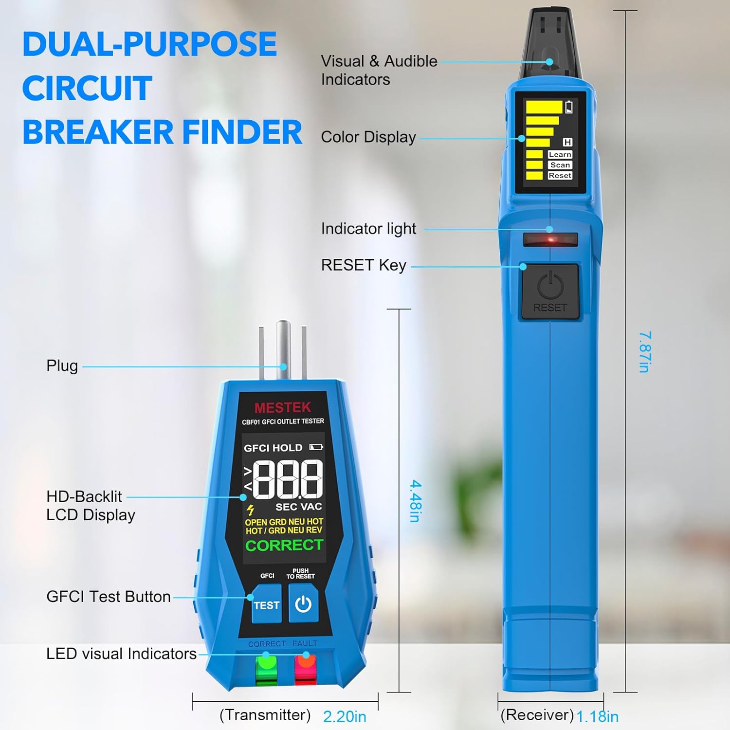
4.1. Receiver (Circuit Breaker Finder)
- Sensing Probe: Detects the signal from the transmitter.
- Detection Indicator Light (Green): Illuminates when a signal is detected.
- Display: Shows signal strength, battery level, and operating mode (Learn, Scan, Reset).
- Detection Signal Indicator Light (Red): Indicates a strong signal or the correct breaker.
- Power Switch/Test Button: Turns the device on/off and initiates scanning/resetting.
4.2. Transmitter (GFCI Outlet Tester)
- Plug: Connects to the electrical outlet.
- HD-Backlit LCD Display: Shows voltage, wiring status, and GFCI test results.
- GFCI Test Button: Initiates the GFCI trip test.
- LED Visual Indicators: Green for correct wiring, Red for fault.
5. Setup
5.1. Battery Installation (Receiver)
- Locate the battery compartment on the back of the Receiver.
- Use the provided screwdriver to open the battery compartment cover.
- Insert two (2) AAA batteries, ensuring correct polarity (+/-).
- Replace the battery compartment cover and secure it with the screw.
The Transmitter does not require separate batteries as it draws power directly from the outlet.
6. Operating Instructions
6.1. Circuit Breaker Finding
This function helps you identify which circuit breaker controls a specific outlet or fixture.
- Step 1: Connect the Transmitter. Plug the Transmitter (outlet tester) into the electrical outlet or fixture you wish to identify the circuit for. Ensure the Transmitter's display shows a correct wiring indication (e.g., "CORRECT" and green LED).
- Step 2: First Scan (Learn Mode). Turn on the Receiver. The screen will display "Learn". Scan all the circuit breakers in your electrical panel by slowly moving the Receiver's sensing probe over each breaker. The Receiver will emit an audible beep and the green indicator light will flash as it detects signals. This step allows the device to learn the unique signal pattern of each breaker.
- Step 3: Second Scan (Scan Mode). After completing the first scan, press the "RESET" button on the Receiver. The screen will now display "Scan". Slowly scan the circuit breakers again. When the Receiver identifies the correct circuit breaker, it will emit a continuous loud beep, the red indicator light will illuminate, and the signal strength bars on the display will maximize.
- Step 4: Verify. To confirm, turn off the identified circuit breaker. The Transmitter should lose power, and its display should turn off.

6.2. GFCI Outlet Testing
The Transmitter can be used independently to test the wiring of an outlet and the functionality of a GFCI outlet.
- Step 1: Plug in the Transmitter. Insert the Transmitter into the 3-prong electrical outlet you wish to test.
- Step 2: Read Wiring Status. Observe the HD-Backlit LCD display and the LED indicators. The display will show the voltage and the wiring condition (e.g., "CORRECT", "OPEN GROUND", "OPEN NEUTRAL", "OPEN HOT", "REVERSED HOT/GROUND", "REVERSED HOT/NEUTRAL", "DUAL OPEN", "NEUTRAL & GROUND"). The green LED indicates correct wiring, while the red LED indicates a fault.
- Step 3: Perform GFCI Test. If the wiring is correct, press the "TEST" button on the Transmitter. A working GFCI outlet should trip (turn off power) immediately.
- Step 4: Reset GFCI. If the GFCI trips, press the "RESET" button on the GFCI outlet to restore power. If the GFCI does not trip, the outlet is faulty and should be serviced by a qualified electrician.


7. Maintenance
- Cleaning: Wipe the device with a dry, soft cloth. Do not use abrasive cleaners or solvents.
- Storage: Store the device in its carrying pouch in a cool, dry place, away from direct sunlight and extreme temperatures.
- Battery Replacement: Replace batteries in the Receiver when the low battery indicator appears on the display to ensure accurate readings.
8. Troubleshooting
| Problem | Possible Cause | Solution |
|---|---|---|
| Receiver does not turn on. | Dead or incorrectly installed batteries. | Check battery polarity or replace with new AAA batteries. |
| Receiver cannot find the correct breaker. | Transmitter not properly connected or signal interference. | Ensure Transmitter is securely plugged into a live outlet. Repeat the "Learn" and "Scan" steps slowly. Minimize other electrical activity during scanning. |
| GFCI test button does not trip the outlet. | Faulty GFCI outlet or incorrect wiring. | Verify outlet wiring with the Transmitter's display. If wiring is correct, the GFCI outlet may be faulty and requires professional inspection. |
| Inconsistent readings. | Low battery in Receiver or external interference. | Replace Receiver batteries. Ensure no other strong electromagnetic fields are nearby. |
9. Specifications
- Model: CBF01
- Operating Voltage: AC 90V~135V
- Operating Frequency: 50Hz~60Hz
- Measurement Accuracy: ±0.1
- Power Source (Receiver): 2 x AAA batteries (included)
- Power Source (Transmitter): Battery Powered (from outlet)
- Item Weight: 177 g (0.39 Pounds)
- Parcel Dimensions: 21.89 x 13.31 x 4.6 cm
- Working Altitude: Up to 2000m
- Security Level: CAT III 135V
- Upper Temperature Rating: 122 Degrees Fahrenheit
- Measurement Type: Circuit Breaker Finder, Outlet Tester with GFCI
10. Warranty and Support
For warranty information or technical support, please refer to the contact details provided with your purchase documentation or visit the official MESTEK website. Keep your purchase receipt as proof of purchase for any warranty claims.