1. Introduction
This manual provides essential instructions for the setup, operation, maintenance, and troubleshooting of the FOSA EC200U C4 P01 Development Board. Designed for professional use, this PCB development board integrates an EC200U LTE Cat 1 telecommunication module with GNSS positioning capabilities, offering a versatile platform for various applications. Please read this manual thoroughly before using the device to ensure proper functionality and safety.
2. Product Overview
The FOSA EC200U C4 P01 Development Board is a robust platform featuring the EC200U LTE Cat 1 telecommunication module. It supports multi-mode and multi-band operations, making it suitable for diverse global applications. Key features include:
- EC200U LTE Cat 1 Module: Provides reliable telecommunication capabilities.
- 40PIN GPIO Interface: Compatible with most Raspberry Pi (RPi) HAT expansion boards for extended functionality.
- GNSS Positioning: Supports GPS, GLONASS, BDS, Galileo, and QZSS for accurate location services.
- Onboard SIM/eSIM Slots: Features Nano SIM and eSIM slots for flexible network connectivity (single mode).
- MIPI Interface: Supports MIPI screens and is compatible with RPi peripherals.
- Camera Interface: Supports customized SPI cameras up to 0.3MP.
- LED Indicators: Five onboard LEDs for monitoring module status.
- Protocol Support: Comprehensive support for TCP, UDP, PPP, NITZ, FILE, MQTT, NTP, HTTP, HTTPS, SSL, FTP, FTPS, CMUX, MMS.

Figure 1: Top-down view of the FOSA EC200U C4 P01 Development Board, highlighting the main components and GPIO header.
3. Setup
Follow these steps to set up your EC200U C4 P01 Development Board:
3.1. Component Identification
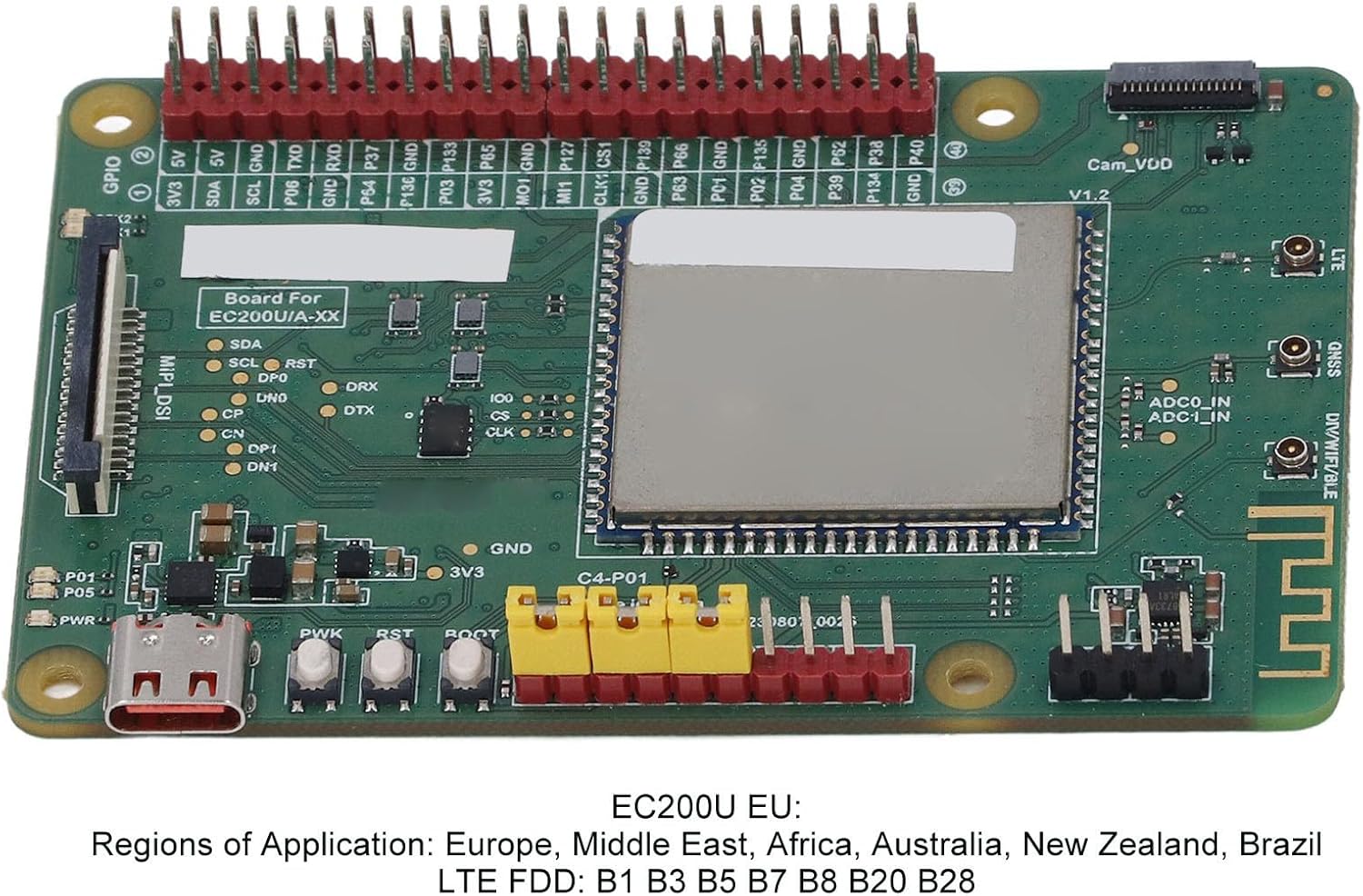
Figure 2: Detailed view of the board's labeled components, including GPIO, power, and module area.
3.2. SIM Card Installation
- Locate the Nano SIM and eSIM slots on the board.
- Carefully insert your Nano SIM card into the designated slot. The board supports single-mode operation for either Nano SIM or eSIM.

Figure 3: Underside of the board, illustrating the SIM card and SD card slot locations.
3.3. Antenna Connection
- Connect the LTE Main Antenna to the corresponding connector on the board.
- If applicable, connect the Diversity Antenna to its designated port.
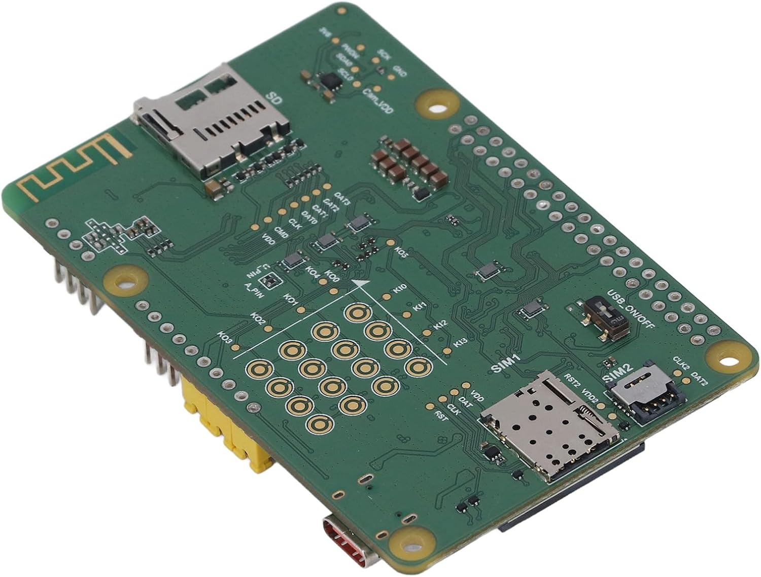
Figure 4: Development board with included accessories, including an antenna and USB cable.
3.4. Power Connection
Connect the development board to a suitable power source using the USB Type-C port. Ensure the power supply meets the board's voltage requirements.
3.5. Initial Power On
Press the PWK key to power on the board. Observe the PWR indicator LED to confirm power status.
3.6. Software Setup
For development and programming, utilize the provided plug-in tools:
- QPYcom
- Thonny IDE
- VSCode
Refer to the respective tool documentation for installation and usage instructions.
4. Operating Instructions
This section outlines the basic operation of the EC200U C4 P01 Development Board.
4.1. Telecommunication Protocols
The board supports a wide range of telecommunication protocols. Depending on your application, configure the module using the appropriate AT commands or software libraries for:
- TCP, UDP, PPP, NITZ, FILE
- MQTT, NTP, HTTP, HTTPS, SSL
- FTP, FTPS, CMUX, MMS
4.2. GNSS Positioning
To utilize GNSS positioning, ensure the GNSS antenna is properly connected. The module can acquire location data from GPS, GLONASS, BDS, Galileo, and QZSS satellite systems. Access positioning data through the module's serial interface or relevant APIs in your application.
4.3. LED Indicators
The onboard LEDs provide visual feedback on the module's status:
- P01: Module Pin 1 status (Default is EC200A XX PWM0).
- P05: NET_MODE Indicator.
- SCK1: SIM1 Detection Indicator (on when SIM1 card is inserted).
- SCK2: SIM2 Detection Indicator (on when SIM2 card is inserted).
- PWR: Power Indicator.
4.4. Key Switches
The board includes several key switches for control:
- PWK: Power On/Off switch.
- RST: Reset button.
- BOOT: Force Download mode.
- USB ON OFF: USB Detection Switch.
5. Maintenance
To ensure the longevity and optimal performance of your FOSA EC200U C4 P01 Development Board, observe the following maintenance guidelines:
- Handling: Always handle the board by its edges to avoid touching components, especially the sensitive module area. Electrostatic discharge (ESD) can damage electronic components; use appropriate ESD precautions.
- Cleaning: Keep the board clean and free from dust and debris. Use a soft, dry brush or compressed air for cleaning. Avoid using liquids or abrasive cleaners.
- Environment: Operate and store the board in a dry, temperature-controlled environment, away from direct sunlight, extreme temperatures, and high humidity.
- Connections: Periodically check all connections (antennas, cables, HATs) to ensure they are secure and free from damage.
6. Troubleshooting
This section addresses common issues you might encounter with the EC200U C4 P01 Development Board.
6.1. No Power Indicator (PWR LED Off)
- Check Power Source: Ensure the USB Type-C cable is securely connected to a functional power source.
- Verify Cable: Try a different USB Type-C cable to rule out a faulty cable.
- Press PWK: Confirm that the PWK (Power) button has been pressed to initiate power-on.
6.2. No Network Connectivity
- SIM Card: Ensure the Nano SIM or eSIM is correctly inserted and activated with a valid data plan. Check the SCK1/SCK2 LEDs.
- Antenna: Verify that the LTE Main Antenna is securely connected.
- Network Coverage: Confirm that you are in an area with adequate LTE Cat 1 network coverage.
- Module Status: Check the P05 (NET_MODE) LED for network activity indication.
6.3. GNSS Not Acquiring Position
- GNSS Antenna: Ensure the GNSS antenna is properly connected and has a clear view of the sky.
- Environment: GNSS performance can be affected by indoor environments, tall buildings, or heavy foliage. Move to an open outdoor area.
6.4. Software Communication Issues
- USB Connection: Ensure the USB cable is connected and the USB ON OFF switch is in the correct position for detection.
- Driver Installation: Verify that necessary USB drivers for the module are installed on your computer.
- IDE/Tool Configuration: Check the serial port settings and module configuration within QPYcom, Thonny IDE, or VSCode.
7. Specifications
Detailed technical specifications for the FOSA EC200U C4 P01 Development Board:
| Feature | Detail |
|---|---|
| Model Number | EC200U C4 P01 |
| LTE TDD Bands | B38, B40, B41 |
| GSM Bands | B2, B3, B5, B8 |
| GNSS Support | GPS, GLONASS, BDS, Galileo, QZSS |
| Bluetooth Version | 4.2 (BR EDR) |
| Wi-Fi Fidelity Scan | 2.4 GHz 11b (Rx) |
| LTE FDD Data Rate | 10 Mbps downlink; 5 Mbps uplink |
| LTE TDD Data Rate | 8.96 Mbps downlink; 3.1 Mbps uplink |
| GSM Data Rate | 85.6 Kbps downlink; 85.6 Kbps uplink |
| NB IoT Support | Not Supported |
| Cat M Support | Not Supported |
| Supported Protocols | TCP, UDP, PPP, NITZ, FILE, MQTT, NTP, HTTP, HTTPS, SSL, FTP, FTPS, CMUX, MMS |
| SIM Card Type | Nano SIM and eSIM (Single Mode) |
| GPIO Interface | 40PIN, RPi HAT compatible |
| MIPI Interface | Yes, RPi peripheral compatible |
| Camera Support | Customized SPI camera, 0.3MP |
| Item Weight | 6.8 ounces (approx. 193g) |
| Package Dimensions | 5.91 x 3.94 x 2.36 inches (approx. 15 x 10 x 6 cm) |

Figure 5: Board detail showing regional application and LTE FDD band support for the EC200U-EU variant.
8. Warranty and Support
Specific warranty terms and conditions for the FOSA EC200U C4 P01 Development Board are not provided within this manual. For detailed warranty information, technical support, or service inquiries, please contact your retailer or the manufacturer directly. Keep your proof of purchase for any warranty claims.


