HUAGZIMO 3 Leaves LED Rotating Gyroscope DIY Kit
HUAGZIMO 3 Leaves LED Rotating Gyroscope DIY Kit
Instruction Manual
1. Introduction
Thank you for choosing the HUAGZIMO 3 Leaves LED Rotating Gyroscope DIY Kit. This kit provides an engaging electronics soldering project, allowing you to assemble a unique rotating gyroscope with multiple LED light patterns. It is designed to enhance soldering skills and familiarize users with electronic components. Please read this manual thoroughly before beginning assembly.

Image 1.1: The assembled 3 Leaves LED Rotating Gyroscope DIY Kit.
2. What's in the Box
Your HUAGZIMO 3 Leaves LED Rotating Gyroscope DIY Kit includes the following components:
- 3 Leaves SMD Soldering Kit (includes PCB, SMD LEDs, resistors, capacitors, MCU chip, tact switch, CR1620 battery clips, bearing, screws, shells, and caps)
- English Installation Instructions

Image 2.1: All components included in the DIY kit, laid out for inspection.
Please verify all components are present before starting assembly. If any components are missing, please contact customer support.
3. Setup and Assembly
This soldering kit requires a foundational understanding of basic electronic theory and welding skills. Children under 14 years of age should perform assembly under adult supervision.
3.1 Tools Required
- Soldering Iron
- Solder Wire
- Tweezers (recommended for SMD components)
- Multimeter (optional, for checking components)
- Small Screwdriver
3.2 Assembly Steps
Follow the markers on the PCB board to install each component. A detailed installation guide is provided with the kit, and you can also scan the QR code on the product packaging for digital instructions.
- Prepare the PCB: Ensure the Printed Circuit Board (PCB) is clean and free of debris.
- Solder SMD Components: Carefully solder the Surface Mount Device (SMD) components, such as the chip resistors, chip capacitors, SMD LEDs, MCU chip, and tact switch, onto their designated pads on the PCB. Refer to the PCB markers (e.g., R1-R11 for chip resistors, D1-D11 for SMD LEDs).
- Install Battery Clips: Solder the CR1620 battery clips (BT1, BT2, BT3) onto the PCB.
- Assemble Bearing: Insert the bearing (CAI-183) into the central opening of the PCB.
- Attach Shells: Place the transparent shells around the assembled PCB and secure them with the provided screws.
- Insert Batteries: Install two CR927 batteries into the battery clips.
- Attach Caps: Secure the caps onto the battery compartments.
Video 3.1: Detailed assembly process for the Rotating Gyroscope DIY Kit, demonstrating soldering of components and final assembly steps.

Image 3.2: The PCB features clear silk screen printing for easy component placement during assembly.
4. Operating Instructions
Once assembled and batteries are installed, the gyroscope is ready for use.
4.1 Powering On and Spinning
To activate the gyroscope, ensure the batteries are correctly inserted. Hold the center bearing between your thumb and forefinger, then use your other hand to spin one of the leaves. The LEDs will illuminate and display various patterns as it rotates.
4.2 Changing Patterns
The gyroscope features multiple pre-programmed LED patterns. You can change the displayed pattern by pressing the tact switch located on the PCB. Each press will cycle through the available patterns.

Image 4.1: The gyroscope in motion, showcasing dynamic LED light patterns.

Image 4.2: Examples of the various light patterns that can be displayed by the gyroscope.
5. Maintenance
5.1 Cleaning
Wipe the gyroscope with a soft, dry cloth. Avoid using harsh chemicals or abrasive materials, as these may damage the plastic shells or electronic components.
5.2 Battery Replacement
The gyroscope uses two CR927 batteries. When the LED lights dim or the gyroscope stops functioning, it's time to replace the batteries. Carefully remove the caps and old batteries, then insert new CR927 batteries, ensuring correct polarity. Replace the caps securely.
5.3 Storage
Store the gyroscope in a cool, dry place away from direct sunlight and extreme temperatures. If storing for an extended period, it is recommended to remove the batteries to prevent leakage.
6. Troubleshooting
| Problem | Possible Cause | Solution |
|---|---|---|
| LEDs do not light up. |
|
|
| Gyroscope does not spin smoothly. |
|
|
| Patterns do not change. |
|
|
7. Specifications
- Product Dimensions: 1 x 0.4 x 4 inches
- Item Weight: 1.44 ounces
- Power Source: 2 x CR927 Nonstandard Batteries (required)
- Recommended Age: 18 years and up (due to soldering requirement)
- LEDs: Multiple SMD LEDs for various light patterns
- Components: SMD resistors, capacitors, MCU chip, tact switch, battery clips, bearing, screws, shells, caps
8. Warranty and Support
For any missing components or issues encountered during assembly or operation, please contact HUAGZIMO customer support. Refer to the contact information provided with your purchase or on the product packaging. We are committed to providing excellent after-sale service.
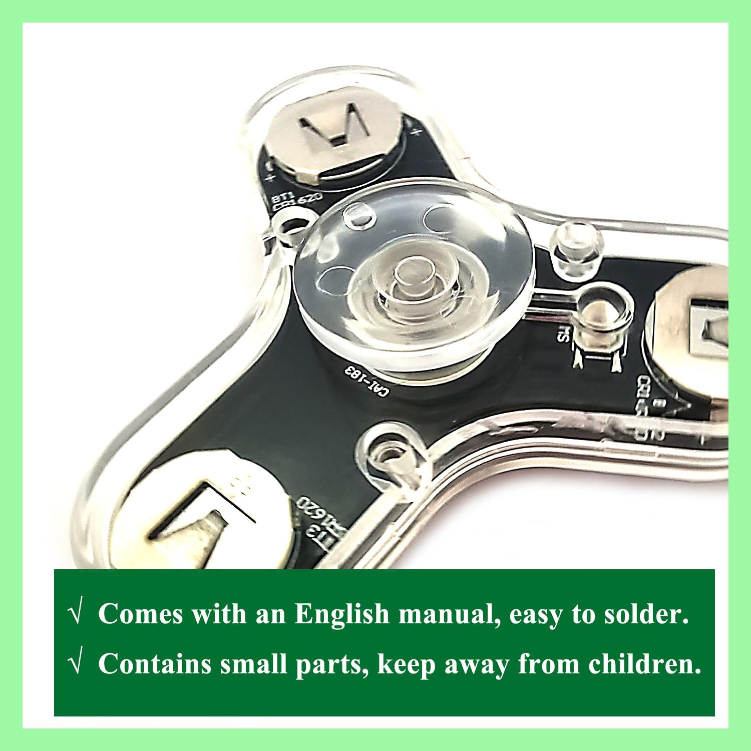
Image 8.1: Important notes regarding the English manual and small parts.
Ask a question about this manual
Ask about setup, troubleshooting, compatibility, parts, safety, or missing instructions. Manuals+ will review the question and use this page’s manual context to help answer it.