1. Introduction
This manual provides detailed instructions for the safe and effective use of the sloHEXtted 6 Channel 12-65V DC Industrial Wireless Crane Radio Remote Control system. This system is designed for controlling electric chain hoists, overhead bridge travelling cranes, and trucks, offering reliable and precise operation with enhanced safety features.
The system includes one transmitter and one receiver, operating within a 12-65V DC range. It features a robust design suitable for demanding industrial environments.
2. Product Features
- 6 Momentary Buttons: The system features 6 momentary buttons. Functions can be customized using a separate USB programming cable (not included).
- Extended Control Range: Offers a control range of up to 100 meters (328 feet) with 360-degree barrier-free operation and strong signal penetration.
- User-Friendly Transmitter: Equipped with 3 low-battery LED indicators for timely battery replacement.
- Enhanced Safety: Features EU standard EMS and a high-quality circuit board for reliable performance. Durable silicone-wrapped buttons provide comfortable operation. An Emergency Stop Button immediately halts all movement when pressed.
- IP65 Rated Durability: The remote control is IP65 dust-proof and waterproof, ensuring excellent performance in harsh environments with high oil pollution, humidity, and dust.
- Easy Pairing and Reprogramming: Software and hardware are fully compatible across the series, simplifying pairing and reprogramming processes.
- Reinforced Construction: The lightweight transmitter and receiver are made from collision-proof PA65 reinforced flame retardant material, featuring 8 anti-collision corners for added durability.

Figure 2.1: Overview of the sloHEXtted Industrial Wireless Crane Radio Remote Control system, showing both the transmitter and receiver units.

Figure 2.2: Detailed view of the transmitter highlighting its humanized design, including LED indicators, silicone buttons, and the Emergency Stop Push Button.

Figure 2.3: Close-up of the EU Standard Emergency Stop button and the reinforced nylon shell with 8 impact-resistant corners, emphasizing product safety and durability.

Figure 2.4: Technical drawing showing the dimensions of both the transmitter and receiver units for installation planning.

Figure 2.5: Illustration demonstrating the 100-meter control range of the remote control in an industrial setting, suitable for various crane types.
3. Setup
3.1 Unpacking and Inspection
Carefully unpack all components and inspect for any signs of damage. Ensure all listed accessories are present. The package typically includes the transmitter, receiver, user manual, and mounting accessories.
Video 3.1: This video demonstrates the unboxing and initial inspection of the industrial radio controller, showcasing its high-quality components and humanized design.
3.2 Powering the Transmitter
The transmitter requires 2 AA batteries (not included). Open the battery compartment on the back of the transmitter and insert the batteries, observing correct polarity. The low-battery LEDs will indicate battery status during operation.
3.3 Receiver Wiring and Mounting
The receiver unit comes with pre-wired Y-type fork terminals for easy connection to your equipment. Refer to the wiring diagram provided on the receiver unit and in the detailed manual for specific connections (e.g., power, UP, DOWN, EAST, WEST, SOUTH, NORTH, RO/START, etc.).
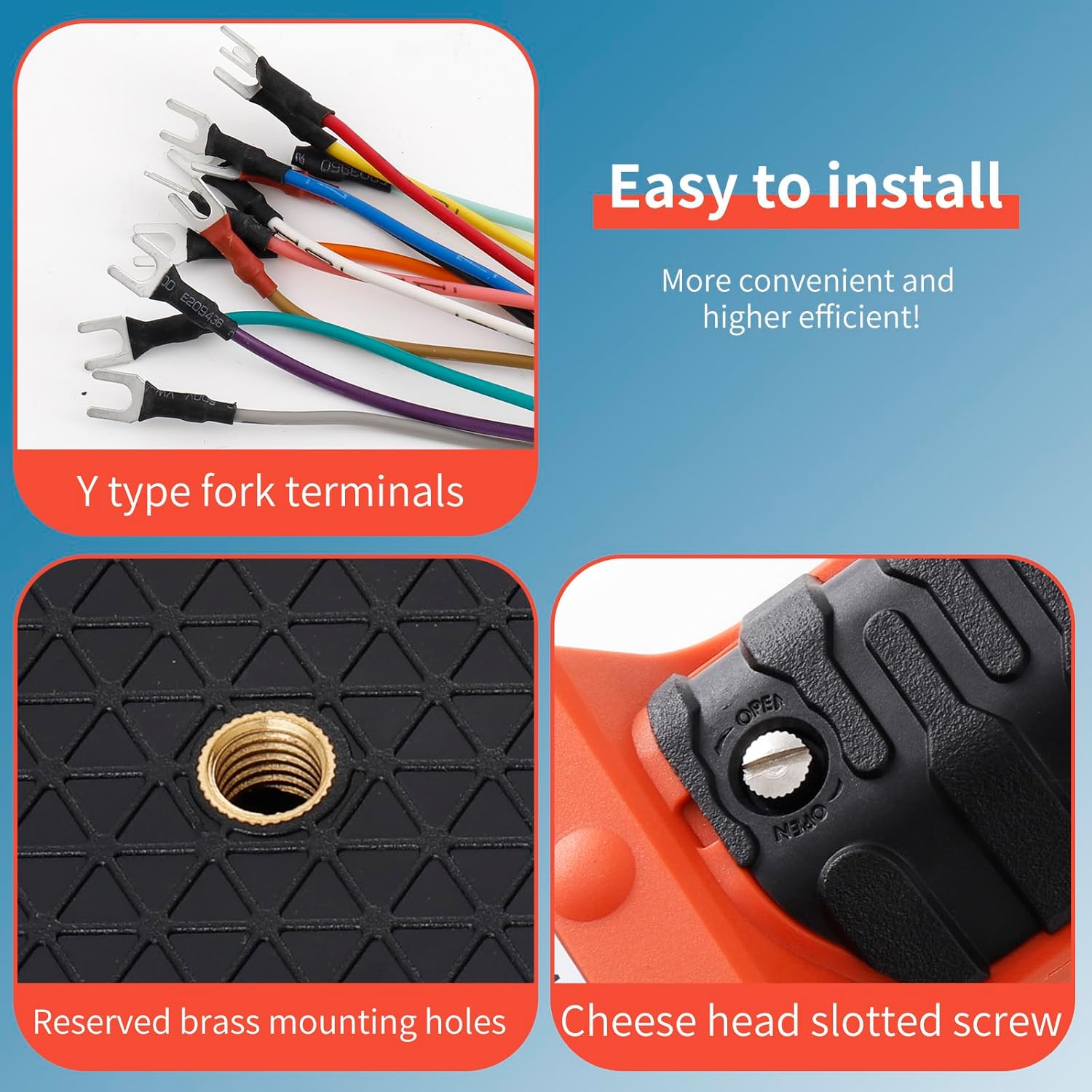
Figure 3.1: Features designed for easy installation, including Y-type fork terminals, reserved brass mounting holes, and a cheese head slotted screw for secure attachment.
The receiver features a brass mounting hole on its back for secure installation. Use the provided spring and bolt for anti-vibration mounting to ensure stable operation.

Figure 3.2: The mounting spring and bolt assembly, designed to provide secure and vibration-resistant installation for the receiver unit.
3.4 Pairing (if necessary)
The transmitter and receiver are typically pre-paired. If re-pairing is required, follow the instructions in the detailed manual. The system is designed for easy pairing and reprogramming.
4. Operating Instructions
4.1 Basic Operation
To begin operation, ensure the Emergency Stop button on the transmitter is disengaged (rotated to release). Press the green START button to activate the transmitter. The status LEDs on both the transmitter and receiver will indicate active connection.

Figure 4.1: Close-up view of the status LEDs on both the transmitter and receiver, indicating operational status and potential errors.
Use the directional buttons (UP, DOWN, EAST, WEST, SOUTH, NORTH) to control the corresponding functions of your equipment. All 6 buttons are momentary, meaning the function is active only while the button is pressed.
Video 4.1: This video demonstrates the durability of the reinforced nylon shell with 8 anti-collision corners, showing the remote control being used in a rugged environment.
4.2 Emergency Stop
In case of an emergency or unexpected movement, immediately press the red Emergency Stop button. This will cut power to the controlled equipment, stopping all operations. To resume, rotate the button to release it and then press the green START button again.
5. Maintenance
Regular maintenance ensures the longevity and reliable operation of your remote control system.
- Cleaning: Wipe down the transmitter and receiver with a damp cloth to remove dust and debris. Avoid using harsh chemicals or abrasive cleaners.
- Battery Replacement: Replace transmitter batteries promptly when the low-battery LED indicators illuminate.
- Inspection: Periodically inspect the unit for any physical damage, especially the silicone buttons and the reinforced shell. Check the wiring connections on the receiver for secure fit and signs of wear.
- Environmental Protection: While the unit is IP65 rated for dust and water resistance, prolonged exposure to extreme conditions should be minimized.
6. Troubleshooting
6.1 Common Issues and Solutions
| Problem | Possible Cause | Solution |
|---|---|---|
| System not responding | Transmitter batteries low/dead; Emergency Stop engaged; Receiver not powered; Out of range; Interference. | Replace batteries; Disengage E-Stop; Check receiver power supply; Move closer to receiver; Check for strong interference sources. |
| Intermittent operation | Weak signal; Partial obstruction; Loose wiring connection. | Ensure clear line of sight; Check all wiring connections on receiver. |
| Specific button not working | Damaged button; Wiring issue for that specific function. | Inspect button for physical damage; Verify wiring for the affected function. |
6.2 Reprogramming Functions
The system's functions can be reprogrammed using a dedicated USB programming cable (sold separately). This allows for customization of button behavior (e.g., momentary, toggle, interlock). Refer to the programming software manual for detailed instructions.
Video 6.1: This video provides a guide on how to reprogram the system of H series Remote Control, demonstrating the software interface for function setting.
7. Specifications
| Specification | Value |
|---|---|
| Manufacturer | sloHEXtted |
| Part Number | industrial radio remote controller |
| Item Weight | 3.03 pounds |
| Product Dimensions | 11 x 8.2 x 3.9 inches |
| Item Model Number | industrial wireless remote control |
| Size | 12-65V DC |
| Color | 1 Transmitter + 1 Receiver |
| Style | 12-65V DC |
| Material | Reinforced flame retardant PA65 material |
| Pattern | 12-65V DC |
| Special Features | Brass mounting hole reserved on receiver back |
| Included Components | Transmitter, Receiver, Accessories (as per package) |
| Batteries Included? | No |
| Batteries Required? | Yes (for transmitter) |
| Date First Available | April 14, 2023 |
8. Warranty and Support
For warranty information and technical support, please contact sloHEXtted directly through their official channels or the retailer from whom the product was purchased. Keep your purchase receipt for warranty claims.