1. Introduction
This manual provides essential instructions for the safe installation, operation, and maintenance of your VEVOR MD750 Automatic Sliding Gate Opener. Please read this manual thoroughly before installation and use to ensure proper function and safety. Keep this manual for future reference.

Figure 1: VEVOR Automatic Sliding Gate Opener Unit
2. Safety Instructions
Your safety and the safety of others are extremely important. Always follow these safety precautions to reduce the risk of injury or damage.
- Ensure all electrical connections comply with local codes and regulations.
- Disconnect power before performing any maintenance or repairs.
- Keep children and pets away from the gate area during operation.
- Do not allow children to play with the gate controls.
- Regularly inspect the gate and opener for signs of wear, damage, or misalignment.
- Ensure safety devices such as infrared sensors are correctly installed and functioning.
- In case of power failure, use the manual release key to operate the gate.

Figure 2: Key Safety Features
3. Package Contents
Verify that all items listed below are included in your package. If any parts are missing or damaged, please contact VEVOR customer service.
- Sliding Gate Opener Unit
- Gear Racks (20 ft / 6 m total length, typically in 10 ft / 3 m sections)
- Remote Controls (Quantity: 2)
- Emergency Release Keys
- Infrared Photocell Sensors
- Mounting Hardware (bolts, washers, brackets, etc.)
- Wireless Keypad (Optional accessory, may be included depending on package)
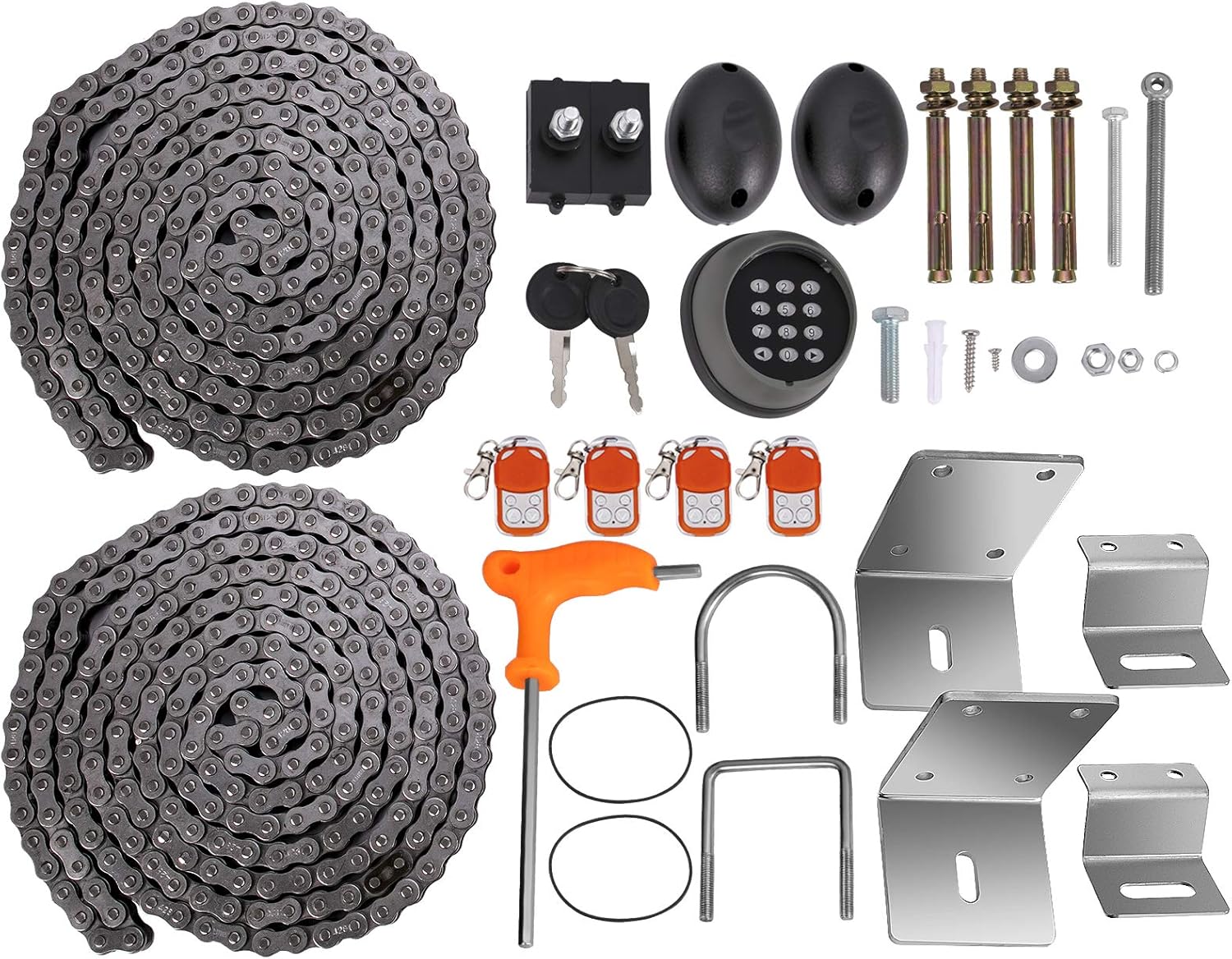
Figure 3: Complete Package Contents
4. Specifications
| Feature | Specification |
|---|---|
| Power Supply | 220 V |
| Max. Gate Weight | 3300 lb / 1497 kg |
| Gear Rack Length | 20 ft / 6 m (two 10 ft / 3 m long chains) |
| Motor Power | 1 HP / 750 W |
| Gate Moving Speed | 12 m/minute |
| Remote Control Distance | 230 ft / 70 m |
| Noise Level | Less than 60 dB |
| Product Dimensions (L x W x H) | 27.4 x 19.8 x 33 cm |
| Product Weight | 20.4 kg |
| Model Number | MD750 |

Figure 4: Gate Opener Dimensions

Figure 5: Motor and Weight Capacity
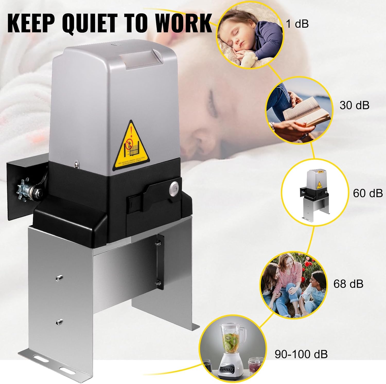
Figure 6: Noise Level Comparison
5. Setup and Installation
5.1 Base Installation
- Prepare a stable concrete base for the gate opener unit. Ensure the base is level and provides adequate support for the unit and gate movement.
- Secure the mounting plate to the concrete base using appropriate anchor bolts.
- Place the gate opener unit onto the mounting plate, aligning the mounting holes.
- Fasten the gate opener to the mounting plate using the provided bolts, washers, and nuts. Ensure all fasteners are tightened securely.
5.2 Gear Rack Installation
- Align the first gear rack section with the opener's pinion gear. Ensure there is a small gap (approx. 1-2mm) between the gear and the rack to allow for smooth operation.
- Mark the drilling points on the gate for the rack's mounting brackets.
- Drill holes and attach the first gear rack section using self-tapping screws and mounting plates. Do not fully tighten the screws yet.
- Insert subsequent gear rack sections, ensuring proper alignment and maintaining the small gap with the pinion gear.
- Once all rack sections are in place, manually move the gate to verify smooth movement across the entire length of the rack without binding.
- Tighten all screws securely.
5.3 Wiring
- Remove the cover of the control board unit.
- Disconnect the power supply terminal (marked PE, N, L) from the control board.
- Connect the live wire (L), neutral wire (N), and ground wire (PE) from your main power supply to the corresponding terminals. Ensure connections are firm and correct.
- Pass the three-conductor wire through the cover and make the connections as indicated in the wiring diagram.
- Reconnect the power supply terminal to the control board.
5.4 Limit Switch Installation
Limit switches define the open and closed positions of your gate.
- Manually move the gate to its fully open position.
- Install the left limit switch on the gear rack, ensuring it will activate the opener's internal limit sensor when the gate is fully open. Secure it with screws.
- Manually move the gate to its fully closed position.
- Install the right limit switch on the gear rack, ensuring it will activate the opener's internal limit sensor when the gate is fully closed. Secure it with screws.
- Test the gate operation to confirm that it stops correctly at both open and closed limits.
5.5 Infrared Sensor Installation
Infrared sensors provide an essential safety feature, preventing the gate from closing if an obstruction is detected.
- Mount the infrared sensors (transmitter and receiver) on opposite sides of the gate opening, ensuring they are at the same height and have a clear line of sight.
- Connect the receiver's V+ to 24V, V- and COM to GND, and NC to IR on the control board.
- Connect the emitter's V+ to 24V and V- to GND on the control board.
- Twist together the emitter's V+ with the receiver's V+ and the emitter's V- with the receiver's V- and COM.
- Connect all the wires to the signal terminal, and re-plug it back in on the control board.
- After installation, block the sensors. If the alarm indicator lights up and the indicator light on the control board turns off, your infrared sensors are correctly installed.

Figure 7: System Components Overview
6. Operating Instructions
6.1 Remote Control Pairing
To pair a new remote control:
- Locate the 'LEARN' button on the control board.
- Press and hold the 'LEARN' button until the corresponding indicator light illuminates.
- Press any button on the remote control twice. The indicator light on the control board will flash to confirm successful pairing.
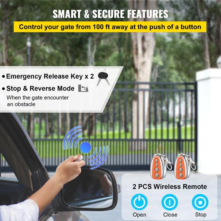
Figure 8: Remote Controls and Emergency Keys
6.2 Functionality Test
After installation and pairing, perform the following tests:
- Limit Switch Test: Operate the gate using the remote control. Ensure the gate stops precisely at the fully open and fully closed positions as set by the limit switches.
- Infrared Sensor Test: While the gate is closing, place an object or your hand in the path of the infrared beam. The gate should immediately stop and reverse direction.
- Remote Control Test: Test all buttons on the remote control (open, close, stop) to ensure they function correctly from various distances within the specified range.
7. Maintenance
Regular maintenance ensures the longevity and safe operation of your gate opener.
- Monthly: Inspect the gate and opener for any loose fasteners, signs of wear, or damage. Clean the gear racks and remove any debris that might obstruct movement.
- Quarterly: Lubricate the gate's moving parts (rollers, hinges) and the opener's chain/gear system with appropriate lubricant. Check the tension of the drive chain.
- Annually: Have a qualified technician inspect the entire system, including electrical connections, safety devices, and motor performance.
8. Troubleshooting
| Problem | Possible Cause | Solution |
|---|---|---|
| Gate does not respond to remote. | No power, remote battery low, remote not paired. | Check power supply, replace remote battery, re-pair remote. |
| Gate stops or reverses unexpectedly. | Obstruction detected by infrared sensors, gate binding. | Clear obstruction, check sensor alignment, inspect gate for binding. |
| Gate does not fully open or close. | Limit switches incorrectly set, gate obstruction. | Adjust limit switches, clear any obstructions. |
| Motor runs but gate does not move. | Manual release engaged, gear rack disengaged or damaged. | Disengage manual release, inspect gear rack for damage or proper engagement. |
9. Warranty and Support
VEVOR products are designed for durability and performance. For warranty information, technical support, or to order replacement parts, please refer to the contact information provided with your purchase or visit the official VEVOR website.
Always provide your product model number (MD750) and purchase date when contacting support.


