1. Introduction
1.1 Product Overview
This manual provides essential information for the safe and efficient operation of your 8.2kW Hybrid Solar Inverter. This multi-function inverter combines the capabilities of an inverter, solar charger, and battery charger into one unit, designed for off-grid solar energy systems.

Figure 1: 8.2kW Hybrid Solar Inverter as part of a home energy storage system. The inverter is shown mounted on a wall, representing its function as a central component in a home energy storage system, converting solar energy for household use.
1.2 Intended Use
The 8.2kW Hybrid Solar Inverter is primarily used in photovoltaic (PV) power generation to convert direct current (DC) generated by solar panels into alternating current (AC) for powering homes and businesses. It can also operate independently for energy storage, meeting diverse energy demands.
2. Safety Instructions
Please read all instructions and warnings carefully before installation and operation. Failure to follow these instructions may result in electric shock, fire, or severe injury.
- Installation must be performed by qualified personnel.
- Ensure all wiring is correctly polarized and securely connected.
- Do not attempt to repair or disassemble the inverter. Contact qualified service personnel.
- Keep the inverter away from flammable materials, moisture, and direct sunlight.
- Ensure adequate ventilation around the inverter to prevent overheating.
- Always disconnect all power sources (PV, battery, AC grid) before performing any maintenance or wiring.
- This device is designed for indoor use only.
3. Product Features
The 8.2kW Hybrid Solar Inverter offers advanced features for reliable and efficient power management:
- 8200W Hybrid Inverter: Off-grid capability with 48VDC to 220/230/240VAC (single phase) output.
- Integrated MPPT Charge Controller: Built-in 160A MPPT charge controller for optimal solar charging.
- High PV Input: Maximum PV no-load voltage of 500VDC; MPPT voltage range of 90~450VDC.
- Pure Sine Wave Output: Provides a stable and clean power supply, suitable for sensitive electronics.
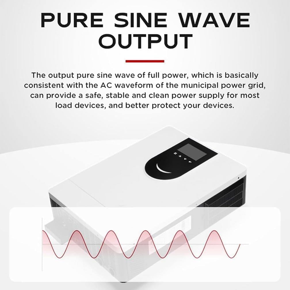
Figure 2: Pure Sine Wave Output. This diagram visually confirms the inverter's pure sine wave output, which ensures a stable and clean power supply, consistent with utility grid power, for sensitive electronic devices.
- Intelligent Design: Equipped with an LCD display and LED indicators for dynamic system data and operating status.
- Remote Monitoring: WIFI and GPRS remote monitoring for iOS and Android, allowing users to monitor the photovoltaic system status anytime, anywhere.
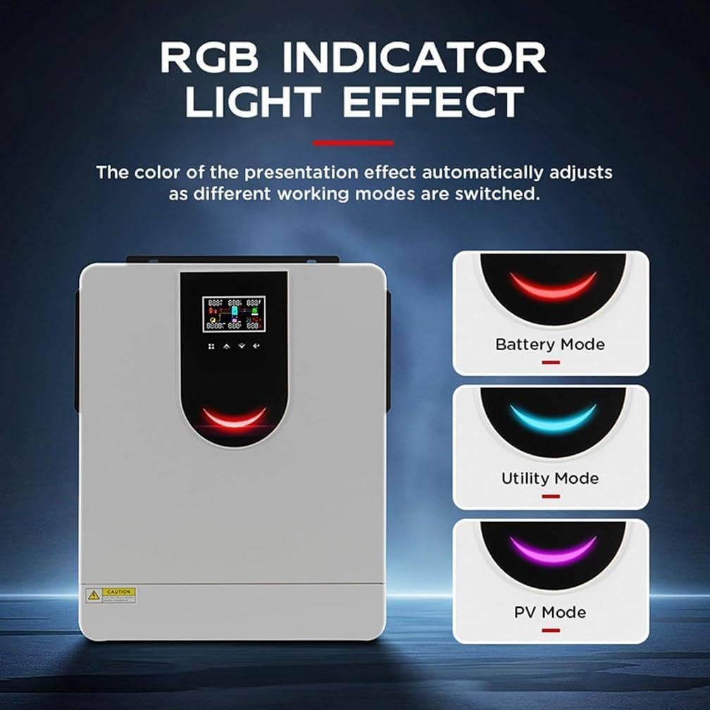
Figure 3: RGB Indicator Light Effect. The image demonstrates the inverter's RGB indicator lights, which change color to signify different operating modes: Battery Mode, Utility Mode, and PV Mode, providing quick visual status updates.
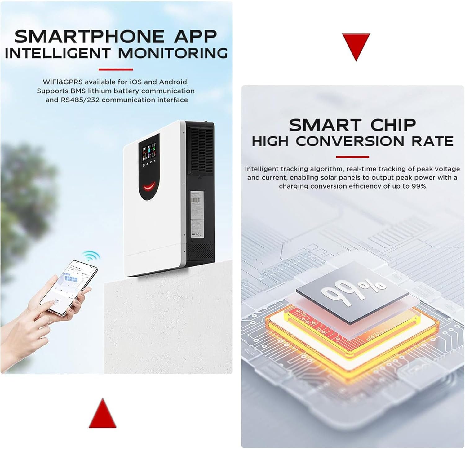
Figure 4: Smartphone App Monitoring and Smart Chip. The image shows the inverter's capability for remote monitoring via a smartphone app (iOS/Android) and emphasizes its smart chip technology, which ensures a high power conversion efficiency of up to 99%.
- Multiple Protection: Features power-off alarm, overload, overcurrent, lightning, low voltage, and short circuit protection.
- Efficient Cooling: High-quality aluminum alloy material with a fan cooling system and porous design for effective heat dissipation.
- Hidden Installation Wiring: Designed for a clean and secure installation with hidden wiring.

Figure 5: LED Display, Fan Cooling, and Hidden Wiring. This image highlights three key design aspects: the large LED display with feedback buttons for user interaction, the efficient fan cooling system for stable operation, and the hidden wiring design for a clean and secure installation.
- Wide Application: Compatible with various household appliances.

Figure 6: Appliance Compatibility. This diagram illustrates the versatility of the inverter, demonstrating its compatibility with a wide range of household appliances.
4. Setup and Installation
4.1 Unpacking
Carefully unpack the inverter and inspect it for any damage. Ensure all components listed in the packing list are present: Solar Inverter (1), Instruction Manual (1).
4.2 Mounting
Mount the inverter on a solid, non-flammable surface in a well-ventilated area, away from direct sunlight and moisture. Ensure sufficient clearance around the unit for proper airflow and heat dissipation.
4.3 System Connection Diagram
Refer to the diagram below for proper system wiring. All connections must be made securely and according to local electrical codes.

Figure 7: System Connection Diagram. A comprehensive diagram illustrating how the inverter connects within a household ON/OFF grid energy storage system, including solar panels, the utility grid, a battery bank, and various AC loads.
4.4 Wiring Instructions
- Battery Connection: Connect the battery bank (48VDC) to the inverter's battery terminals. Ensure correct polarity.
- PV Input Connection: Connect the solar panel array to the PV input terminals. Observe the maximum PV input voltage (500VDC) and MPPT voltage range (90-450VDC).
- AC Input Connection (Grid/Generator): Connect the AC utility grid or a compatible generator to the AC input terminals.
- AC Output Connection: Connect your household loads to the AC output terminals.
- Grounding: Ensure the inverter is properly grounded according to local regulations.
5. Operating Instructions
5.1 Initial Startup
- After all connections are made and verified, switch on the battery breaker.
- Switch on the PV array breaker.
- Switch on the AC input breaker (if connected to grid/generator).
- Switch on the AC output breaker to power your loads.
- The inverter will perform a self-test and then begin operation.
5.2 LCD Display and Indicators
The inverter features an LCD display and three LED indicators to show real-time system status and data. Use the feedback buttons to navigate through the display menus and view parameters such as input/output voltage, current, power, battery status, and operating mode.
5.3 Monitoring via App
Download the dedicated mobile application (available for iOS and Android) to monitor your inverter remotely. The app provides real-time data, historical performance, and allows for certain settings adjustments via WIFI or GPRS connection.
6. Maintenance
Regular maintenance ensures optimal performance and longevity of your inverter:
- Cleaning: Periodically clean the inverter's exterior with a dry cloth. Ensure ventilation openings are free from dust and debris.
- Connections: Annually check all electrical connections for tightness and corrosion.
- Environment: Ensure the operating environment remains within specified temperature and humidity ranges.
- Battery Inspection: Regularly inspect battery terminals for corrosion and ensure battery health.
- Firmware Updates: Check for available firmware updates through the mobile app or manufacturer's website.
7. Troubleshooting
This section provides solutions for common issues. For problems not listed here, contact customer support.
| Problem | Possible Cause | Solution |
|---|---|---|
| Inverter not turning on | No battery power; DC input switch off; Faulty wiring | Check battery connections and voltage; Ensure DC switch is ON; Verify all wiring. |
| No AC output | Overload; Short circuit; AC output breaker off; Low battery voltage | Reduce load; Check for short circuits; Turn on AC output breaker; Charge batteries. |
| PV input not charging | PV array disconnected; Insufficient sunlight; PV input voltage too low/high | Check PV connections; Ensure adequate sunlight; Verify PV voltage is within MPPT range. |
| Overheat alarm | Blocked ventilation; Excessive ambient temperature; Overload | Clear obstructions; Ensure proper ventilation; Reduce ambient temperature; Reduce load. |
| Inverter beeping | Warning or fault condition (e.g., low battery, overload) | Check LCD display for error codes and refer to the manual's error code section (if applicable) or contact support. |
8. Technical Specifications
Detailed specifications for the 8.2kW Hybrid Solar Inverter:

Figure 8: Inverter with Key Specifications. This image displays the 8.2kW Hybrid Solar Inverter and its primary technical specifications, including model, MPPT voltage, current, PV range, and dimensions.
| Parameter | Value |
|---|---|
| Model | 8.2kW (SY-8.2KW) |
| Rated Output Power | 8200W |
| Surge Power | 16400W |
| Maximum Solar Charge Current | 160A |
| PV Input (DC) - Rated/Max Voltage | 360VDC / 500VDC |
| PV Input (DC) - Start-up/Initial Supply Voltage | 90VDC / 120VDC |
| PV Input (DC) - MPPT Voltage Range | 90VDC~450VDC |
| Number of MPPT Trackers / Max Input Current | 1 / 27A |
| Grid Output (AC) - Rated Output Voltage | 220/230/240VAC |
| Grid Output (AC) - Output Voltage Range | 195-253VAC |
| Grid Output (AC) - Rated Output Current | 35.6A/44.3A |
| Two-Load Output Power (Battery Mode) | Max 2733W |
| AC Input - Start-up/Auto-Restart Voltage | 120-140VAC / 180VAC |
| AC Input - Acceptable Input Voltage Range | 170-280VAC or 280VAC |
| Maximum AC Output Current | 40A |
| Nominal Operating Frequency | 50/60Hz |
| Battery Output (AC) - Nominal Output Voltage | 48VDC |
| Output Waveform | Pure Sine Wave |
| Efficiency (DC to AC) | 94% |
| Rated DC Voltage | 48V DC |
| Maximum AC Charging Current | 140A |
| Product Size (L*W*H) | 555*405*135mm |
| Weight | 14.2kg (34.5 pounds) |
| Communication Port | RS232/WIFI/Remove LCD/GPRS |
9. Warranty and Support
Warranty information for this product is typically provided at the time of purchase or included with the product packaging. Please refer to your purchase documentation for specific warranty terms and conditions.
For technical support, service, or warranty claims, please contact your retailer or the manufacturer directly using the contact information provided with your purchase.