1. Introduction
This manual provides detailed instructions for the installation, configuration, and operation of your ASRock Z890 Taichi OCF ATX Motherboard. Designed for Intel Core Ultra Processors (Series 2) with an LGA1851 socket, this motherboard offers advanced features for high-performance computing and overclocking.
Please read this manual thoroughly before beginning the installation process to ensure proper setup and to maximize the performance and stability of your system.
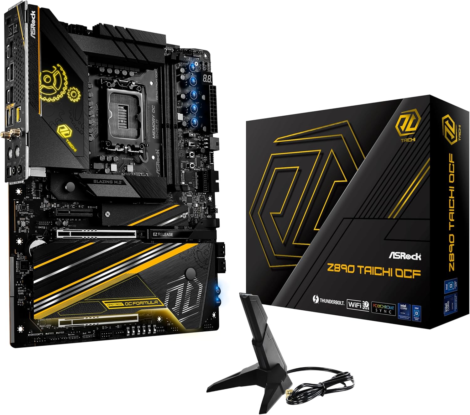
Figure 1.1: ASRock Z890 Taichi OCF Motherboard, retail packaging, and included WiFi antenna.
2. Key Features
The ASRock Z890 Taichi OCF motherboard is engineered with several advanced features to support demanding applications and overclocking:
- Processor Support: Compatible with Intel Core Ultra Processors (Series 2) utilizing the LGA1851 socket.
- Power Delivery: Features a robust 22+1+2+1+1 Power Phase design with 110A SPS for VCore, ensuring stable power delivery for extreme overclocking.
- Memory Configuration: Equipped with 2 x DDR5 DIMM slots, supporting Dual Channel memory up to 10133+ (OC) and a maximum capacity of 128 GB. This 1-DIMM per channel configuration is optimized for superior memory overclocking headroom.
- Graphics Output: Includes 2 Thunderbolt 4 Type-C ports for high-speed data transfer and display connectivity.
- Overclocking Tools: Integrates BIOS Flashback for easy firmware updates, Memory OC Shield for enhanced memory stability, 20K Capacitors with 1000uF capacitance for durability, and a Professional Overclocking Toolkit.
- Advanced Cooling: Features a hybrid VRM heatsink, multi-layer M.2 heatsinks, and a chipset heatsink for efficient thermal management of critical components.
- Connectivity: Supports multiple M.2 sockets for high-speed storage, 5Gbps LAN, and WiFi 7 for advanced wireless networking.

Figure 2.1: Detailed top-down view of the ASRock Z890 Taichi OCF Motherboard, highlighting component layout.
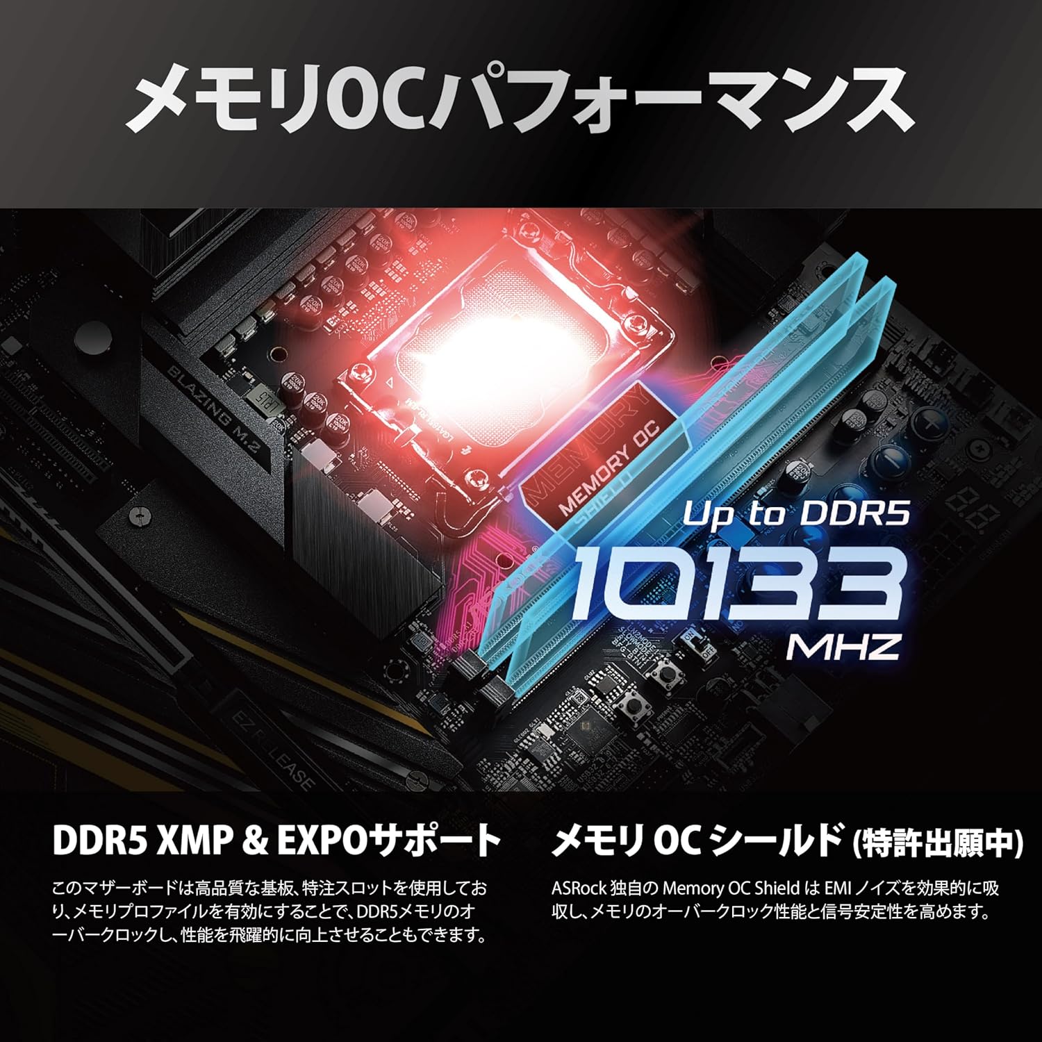
Figure 2.2: Illustration of the motherboard's memory overclocking capabilities, supporting DDR5 up to 10133 MHz.

Figure 2.3: Visual representation of the motherboard's robust power delivery system and high-quality PCB construction.

Figure 2.4: Overview of the motherboard's comprehensive SSD and VRM cooling solutions.

Figure 2.5: Display of the various high-speed interfaces available on the motherboard, including storage, wired, and wireless connectivity.

Figure 2.6: Illustration of user-friendly features such as GPU release mechanism, dedicated overclocking buttons, durable capacitors, and the BIOS Flashback function.
3. Setup and Installation
Before installing the motherboard, ensure your system case is compatible with the ATX form factor. Always handle the motherboard by its edges and wear an anti-static wrist strap to prevent electrostatic discharge (ESD) damage.
3.1. Installing the CPU
- Locate the LGA1851 CPU socket on the motherboard.
- Open the CPU socket lever and remove the protective cover.
- Carefully align your Intel Core Ultra Processor (Series 2) with the socket, ensuring the gold triangle on the CPU matches the indicator on the socket.
- Gently place the CPU into the socket without applying force.
- Close the CPU socket lever to secure the processor.
- Install your CPU cooler according to its manufacturer's instructions.
3.2. Installing DDR5 Memory
- Locate the two DDR5 DIMM slots on the motherboard.
- Open the clips at both ends of the memory slot.
- Align the notch on the DDR5 memory module with the key in the DIMM slot.
- Insert the memory module firmly into the slot until the clips snap into place. Ensure both clips are closed.
3.3. Installing M.2 SSDs
- Identify the M.2 slots on your motherboard.
- Remove the M.2 heatsink and stand-off screw from the desired slot.
- Insert the M.2 SSD into the slot at a 30-degree angle.
- Gently push down the SSD and secure it with the stand-off screw.
- Reinstall the M.2 heatsink, ensuring proper contact for thermal dissipation.
3.4. Connecting Power Supply
- Connect the 24-pin ATX power connector from your power supply to the corresponding header on the motherboard.
- Connect the 8-pin (or 4+4-pin) CPU power connector(s) to the CPU power headers near the CPU socket.
3.5. Installing the Motherboard into the Case
- Install the I/O shield into the case's rear opening.
- Carefully place the motherboard into the case, aligning the screw holes with the standoffs.
- Secure the motherboard with screws. Do not overtighten.

Figure 3.1: The ASRock Z890 Taichi OCF Motherboard and its complete set of accessories, including cables and manuals.
4. Operating Instructions
4.1. Initial Boot and BIOS Access
After completing the hardware installation, connect your display, keyboard, and mouse. Power on your system.
- To enter the BIOS/UEFI setup utility, press the Del or F2 key during the Power-On Self-Test (POST) phase.
- The BIOS allows you to configure system settings, boot order, and monitor hardware status.
- For advanced overclocking features, refer to the dedicated sections within the BIOS/UEFI interface.
4.2. Driver Installation
After installing your operating system, install the necessary drivers for the motherboard components. These typically include chipset drivers, LAN drivers, audio drivers, and WiFi/Bluetooth drivers. Drivers can be found on the ASRock support website for your specific motherboard model.
4.3. Thunderbolt 4 Connectivity
The motherboard features two Thunderbolt 4 Type-C ports. These ports support high-speed data transfer, display output, and power delivery. Ensure you use certified Thunderbolt 4 cables for optimal performance.

Figure 4.1: The rear input/output panel, showing various ports including USB, Thunderbolt 4 Type-C, Ethernet, and audio jacks.
5. Maintenance
5.1. BIOS Updates
ASRock regularly releases BIOS updates to improve system stability, add new features, and enhance compatibility. It is recommended to keep your BIOS updated to the latest version.
- BIOS Flashback: This motherboard supports BIOS Flashback, allowing you to update the BIOS without a CPU, RAM, or graphics card installed. Download the latest BIOS file from the ASRock website, rename it as specified in the BIOS Flashback instructions, place it on a USB drive, and use the dedicated BIOS Flashback port and button on the rear I/O panel.
- In-OS Update: ASRock provides utilities for updating the BIOS directly from within your operating system.
- Instant Flash: You can also update the BIOS from within the BIOS/UEFI setup utility using a USB flash drive.
Caution: Incorrect BIOS updates can damage your motherboard. Follow ASRock's official instructions carefully.
5.2. Cleaning
Regularly clean your computer's interior to prevent dust buildup, which can lead to overheating and reduced performance. Use compressed air to remove dust from heatsinks, fans, and other components. Ensure the system is powered off and unplugged before cleaning.
6. Troubleshooting
This section provides solutions to common issues you might encounter.
6.1. No Power / No Boot
- Ensure all power cables (24-pin ATX, 8-pin CPU) are securely connected to the motherboard and power supply.
- Verify the power supply is switched on and connected to a working power outlet.
- Check front panel connections (power button, reset button) to ensure they are correctly plugged into the motherboard headers.
- Try clearing the CMOS (Complementary Metal-Oxide-Semiconductor) by removing the CMOS battery for a few minutes or using the CLR CMOS button/jumper if available.
6.2. No Display Output
- Confirm your monitor is connected to the correct graphics output (either integrated graphics on the motherboard or a dedicated graphics card).
- Reseat your graphics card and memory modules.
- Test with a single RAM stick in different slots.
- Ensure your display cable is securely connected at both ends.
6.3. Network Connectivity Issues (LAN/WiFi)
- Wired LAN: Check the Ethernet cable connection. Ensure LAN drivers are installed. Verify network settings in your operating system.
- WiFi 7: Ensure the WiFi antennas are securely connected to the rear I/O panel. Install the latest WiFi drivers. Check network settings and ensure you are connecting to the correct network.
7. Specifications
| Feature | Specification |
|---|---|
| Brand | ASRock |
| Model Name | Z890 TAICHI OCF |
| CPU Socket | LGA 1851 |
| Compatible Processors | Intel Core Ultra (Series 2) |
| Chipset Type | Intel Z890 |
| RAM Memory Technology | DDR5 |
| Memory Clock Speed | 10133 MHz (OC) |
| Memory Storage Capacity | 128 GB |
| Compatible Devices | Personal Computer |
| Platform | Windows 11 |
| Product Dimensions | 14 x 11 x 3 inches |
| Item Weight | 4.4 pounds |
| Manufacturer | ASRock |
8. Warranty and Support
Your ASRock Z890 Taichi OCF Motherboard is covered by a manufacturer's warranty. For detailed information regarding warranty terms, conditions, and duration, please refer to the warranty card included with your product or visit the official ASRock website.
For technical support, driver downloads, BIOS updates, and frequently asked questions, please visit the ASRock support page:
When contacting support, please have your motherboard model (Z890 TAICHI OCF) and serial number ready.