
1. Introduction
This manual provides detailed instructions for the installation, operation, and maintenance of the WPTGODGB AVP-40 and AVP-63 Adjustable Overvoltage, Undervoltage, and Overcurrent Protector Relays. These devices are designed to protect electrical circuits and equipment from damage caused by voltage fluctuations and excessive current, ensuring stable and safe operation. Please read this manual thoroughly before installation and use.
2. Product Features
The AVP-40/AVP-63 protector relay offers comprehensive protection and monitoring capabilities:
- Overvoltage Protection: Automatically disconnects the circuit when voltage exceeds a set limit.
- Undervoltage Protection: Automatically disconnects the circuit when voltage drops below a set limit.
- Overcurrent Protection: Automatically disconnects the circuit when current exceeds a set limit.
- Automatic Reclosing: Automatically restores power after a fault condition clears and a set delay expires.
- Voltage Display: Real-time display of the current line voltage.
- Current Display: Real-time display of the current load current.
- Adjustable Parameters: User-configurable settings for overvoltage, undervoltage, overcurrent thresholds, and reclosing delays.
3. Setup and Installation
Safety Precautions: Before installation, ensure that the main power supply is disconnected to prevent electric shock. Installation should be performed by a qualified electrician in accordance with local electrical codes and regulations.
3.1 Mounting
The AVP-40/AVP-63 is designed for DIN rail mounting. Securely attach the device to a standard 35mm DIN rail within an electrical enclosure.

Figure 1: Front view of the AVP-40/AVP-63 Protector Relay, illustrating the digital display and control interface.
3.2 Wiring Diagram
Connect the device according to the following general wiring principles. Refer to the specific diagram printed on the device or its packaging for precise terminal identification.
- Input (Line): Connect the incoming live (L) and neutral (N) wires from the main power supply to the designated input terminals.
- Output (Load): Connect the live (L) and neutral (N) wires leading to the protected load (e.g., appliances, circuits) to the designated output terminals.
- Ensure all connections are tight and secure to prevent loose contacts and overheating.
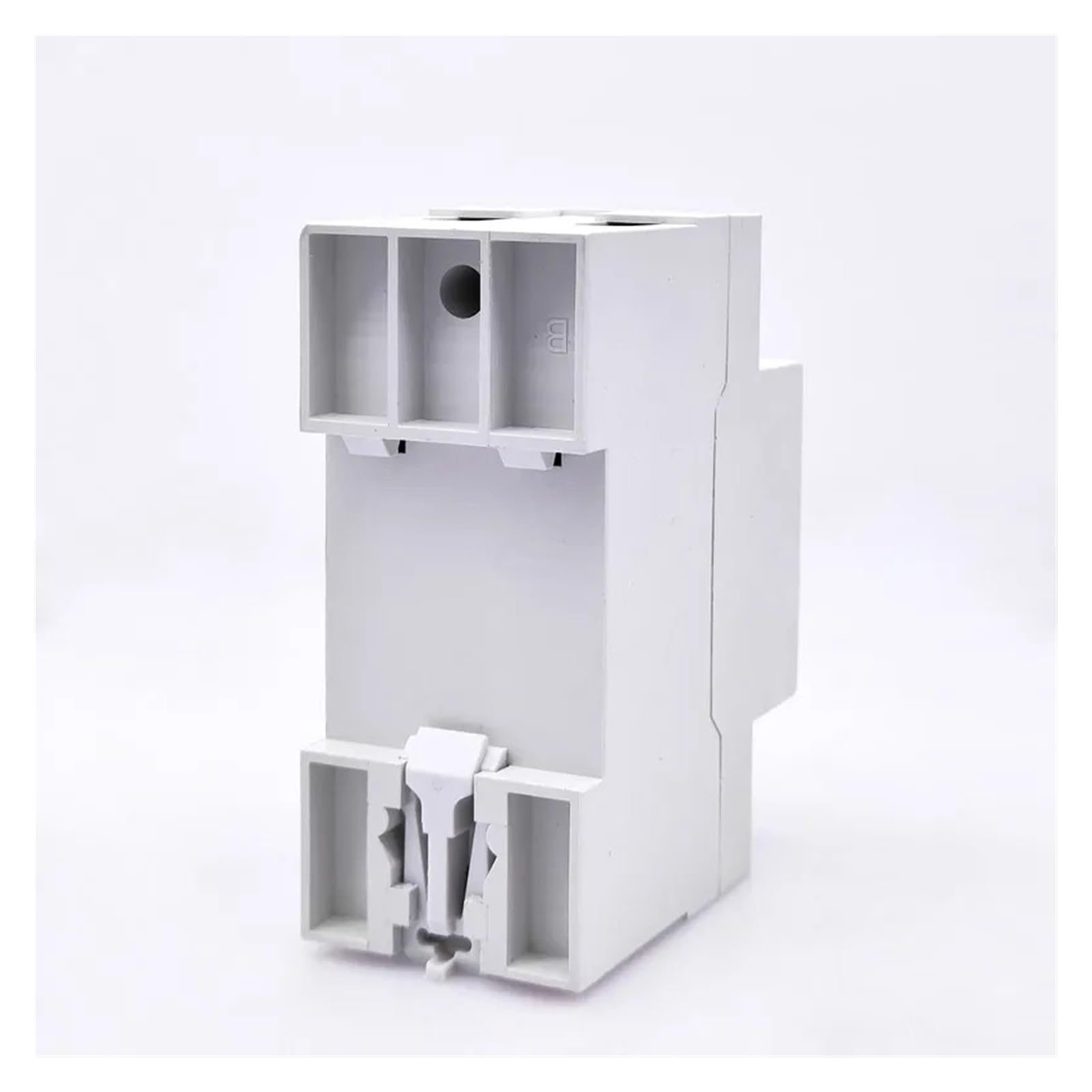
Figure 2: Side view of the AVP-40/AVP-63 Protector Relay, highlighting the input and output terminal connections for wiring.
4. Operating Instructions
After successful installation and power-up, the device will display the current voltage and current. Use the control buttons (typically 'SET', 'UP', 'DOWN') to navigate menus and adjust parameters.
4.1 Display Modes
- Normal Mode: Displays real-time voltage (V) and current (A) alternately.
- Fault Mode: Displays fault codes (e.g., 'OV' for overvoltage, 'UV' for undervoltage, 'OC' for overcurrent) when a protection event occurs.
4.2 Parameter Settings
Press the 'SET' button to enter the parameter setting mode. Use 'UP' and 'DOWN' buttons to adjust values and 'SET' again to confirm and move to the next parameter. If no button is pressed for a few seconds, the device will exit setting mode.
- Overvoltage Protection Value (OV): Set the maximum allowable voltage. Range: 230V-300V (Default: 270V).
- Undervoltage Protection Value (UV): Set the minimum allowable voltage. Range: 140V-210V (Default: 170V).
- Overcurrent Protection Value (OC): Set the maximum allowable current. Range: 1A-40A (for AVP-40) or 1A-63A (for AVP-63) (Default: 40A/63A).
- Reclosing Delay Time (dLY): Set the delay before automatic reclosing after a fault clears. Range: 5s-300s (Default: 30s).
- Recovery Delay Time (rEC): Set the delay before the device attempts to reclose after a protection event. Range: 1s-60s (Default: 5s).
5. Maintenance
The AVP-40/AVP-63 protector relay is designed for minimal maintenance. However, regular checks can ensure optimal performance and longevity.
- Visual Inspection: Periodically inspect the device for any signs of physical damage, discoloration, or loose connections.
- Cleaning: Keep the device free from dust and debris. Use a soft, dry cloth for cleaning. Do not use liquid cleaners.
- Connection Check: Ensure all wiring connections remain tight and secure. Loose connections can lead to overheating and malfunction.
- Functionality Test: If possible, periodically test the protection functions by simulating fault conditions (e.g., using a variable power supply) to ensure the device responds correctly.
6. Troubleshooting
Refer to the table below for common issues and their potential solutions.
| Problem | Possible Cause | Solution |
|---|---|---|
| Device does not power on. | No input power; incorrect wiring; device fault. | Check main power supply. Verify wiring connections. If problem persists, contact support. |
| Device trips frequently. | Voltage/current outside set limits; sensitive settings. | Check actual voltage/current. Adjust OV/UV/OC settings if necessary, ensuring they are appropriate for your load. |
| Device does not reclose. | Fault condition still present; reclosing delay too long; device fault. | Ensure fault condition has cleared. Check reclosing delay (dLY) setting. Manually reset if needed. |
| Display shows 'OV', 'UV', or 'OC'. | Overvoltage, undervoltage, or overcurrent detected. | Identify and rectify the cause of the voltage/current anomaly. The device will reclose automatically after the fault clears and delay expires. |
| Inaccurate voltage/current readings. | Calibration issue; external interference. | Verify readings with a calibrated multimeter. If significant discrepancy, contact support. |
7. Specifications
| Parameter | Value |
|---|---|
| Model | AVP-40, AVP-63 |
| Rated Voltage | 230VAC |
| Frequency | 50/60Hz |
| Maximum Load Current (AVP-40) | 40A (Adjustable 1-40A) |
| Maximum Load Current (AVP-63) | 63A (Adjustable 1-63A) |
| Overvoltage Protection Range | 230V-300V (Adjustable) |
| Undervoltage Protection Range | 140V-210V (Adjustable) |
| Reclosing Delay Time | 5s-300s (Adjustable) |
| Recovery Delay Time | 1s-60s (Adjustable) |
| Display | Dual Digital Display (Voltage, Current) |
| Mounting | 35mm DIN Rail |
| Item Weight | 50 Grams |
| Manufacturer | WPTGODGB |
8. Warranty and Support
Information regarding product warranty and customer support channels was not provided in the available product data. Please refer to the product packaging or contact your point of purchase for details on warranty coverage and technical assistance.