1. Introduction
This instruction manual provides comprehensive guidance for the chenyang USB C DIY Connector Kit, Model CY-CN-032. This kit is designed for users with manual soldering proficiency to replace existing Micro USB 5Pin connectors with USB-C female sockets, enabling modern connectivity for various devices. The kit includes both standard and reversible pinout connectors to suit different application requirements.
2. Package Contents
The chenyang USB C DIY Connector Kit (CY-CN-032) includes the following components:
- 5 x USB-C Female Sockets (Standard Pinout, marked MC002)
- 5 x USB-C Female Sockets (Reversible Pinout, marked FMC002)

3. Features
- Dual Pinout Options: Includes both standard (MC002) and reversible (FMC002) pinout configurations for versatile application.
- Micro USB Replacement: Designed to replace existing Micro USB connectors on various electronic devices.
- Data Transmission: Supports USB 2.0 data transmission speeds.
- Power Delivery: Supports power supply up to DC 5V 2A.
- OTG Support: Compatible with On-The-Go (OTG) functionality for connecting peripherals like mice and keyboards.
- Wide Compatibility: Suitable for use with various peripherals including mice, keyboards, phones, and speakers.
4. Safety Information
WARNING: This product requires manual soldering. Improper soldering techniques can lead to device damage, electrical shorts, or personal injury. Only proceed if you possess adequate manual soldering skills and equipment.
- Always work in a well-ventilated area.
- Use appropriate personal protective equipment, including safety glasses.
- Ensure the device is powered off and disconnected from all power sources before beginning any work.
- Use a soldering iron with a fine tip suitable for small surface-mount components.
- Avoid overheating components.
- Verify all connections for shorts or cold solder joints before reassembling and powering on the device.
5. Installation Guide
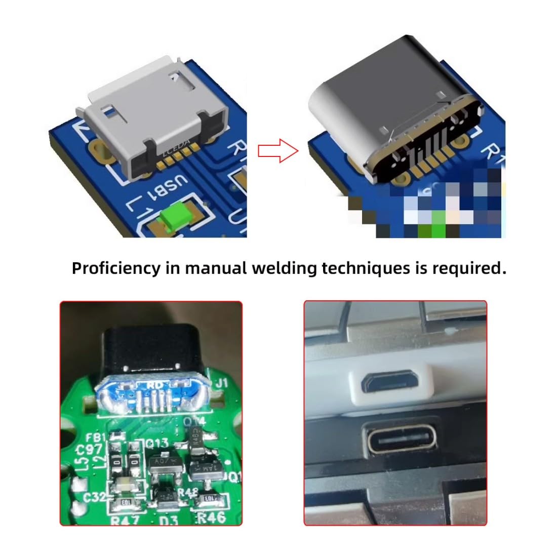
The installation process involves desoldering the existing Micro USB connector and carefully soldering the new USB-C DIY connector in its place. Proficiency in manual soldering techniques, especially for small components, is essential.
5.1. Tools Required
- Soldering Iron with fine tip
- Solder (preferably thin gauge)
- Flux
- Desoldering wick or pump
- Tweezers
- Magnification (e.g., magnifying lamp, microscope)
- Multimeter for continuity checks
5.2. Step-by-Step Procedure
- Disassemble Device: Carefully open your device and locate the Micro USB port to be replaced. Disconnect any cables or components that may obstruct access.
- Desolder Micro USB: Using your soldering iron and desoldering tools, carefully remove the existing Micro USB connector from the circuit board. Ensure all solder pads are clean and free of residual solder.
- Prepare USB-C Connector: Identify whether your application requires a standard pinout (MC002) or reversible pinout (FMC002) connector. Refer to the pinout diagrams below.
- Align and Solder: Carefully align the new USB-C DIY connector with the cleaned solder pads on the circuit board. Solder each pin, ensuring good electrical contact and no solder bridges between adjacent pins. A microscope or strong magnification is highly recommended for this step.
- Verify Connections: After soldering, use a multimeter to check for continuity between the USB-C connector pins and their corresponding traces on the circuit board. Also, check for any short circuits between adjacent pins.
- Reassemble Device: Once all connections are verified, carefully reassemble your device.


5.3. Pinout Diagrams
Understanding the pinout is crucial for correct installation. The kit includes connectors with two different pinout configurations:
- Standard Pinout (MC002): Typically used when the original Micro USB ID pin was connected to ground.
- Reversible Pinout (FMC002): May be required for devices where the Micro USB ID pin was not tied to ground, to ensure proper OTG functionality or charging.

Note on USB OTG ID: Some devices tie the USB ID pin to ground to indicate host mode. If your device does not charge or connect after conversion, you may need to investigate the original ID pin configuration and potentially modify the circuit board (e.g., cut a trace) to ensure the device correctly recognizes the USB-C connection as a peripheral or charging port.
6. Operation
Once the USB-C DIY connector is successfully installed, your device will function with a USB-C port. This allows for:
- Charging: Connect a compatible USB-C charger for power delivery up to 5V 2A.
- Data Transfer: Connect to a computer or other devices using a USB-C cable for USB 2.0 data transmission.
- Peripheral Connectivity: Utilize OTG functionality to connect USB-C compatible peripherals such as mice, keyboards, or external storage devices.

7. Specifications
| Model Number | CY-CN-032 |
| Connector Type | USB Type C Female |
| Pinout Configurations | Standard (MC002), Reversible (FMC002) |
| Data Transmission | USB 2.0 |
| Power Supply Support | DC 5V 2A (maximum) |
| OTG Support | Yes |
| Dimensions (approx.) | 9.7mm (length) x 5.5mm (width) x 3.4mm (height of PCB) |
| Item Weight | 0.176 ounces (per 10-pack) |
| Color | Black (connector housing) |

8. Troubleshooting
- Device not charging or connecting:
- Check all solder joints for continuity and shorts using a multimeter.
- Ensure the correct pinout (standard vs. reversible) was used for your specific device.
- Investigate if the original Micro USB ID pin on your device's PCB was tied to ground. If so, the device might be stuck in host mode. This may require advanced modification to the PCB (e.g., cutting a trace) to resolve.
- Verify that the USB-C cable and power adapter used are functional and compatible.
- Physical damage to connector or PCB:
- Inspect the connector and surrounding PCB area for any physical damage, bent pins, or lifted pads that may have occurred during soldering.
- If damage is significant, replacement of the connector or further PCB repair may be necessary.
9. Warranty and Support
For warranty information or technical support regarding the chenyang USB C DIY Connector Kit, please refer to the seller's policies on the platform where the product was purchased. Due to the DIY nature of this product and the requirement for manual soldering, successful installation and functionality are highly dependent on user skill and proper technique. The manufacturer is not responsible for damage caused by improper installation.