1. Safety Information
Please read this manual thoroughly before installation, operation, or maintenance of the QLWAHK Inverter 9600 Series Variable Frequency Drive. Failure to follow these instructions may result in serious injury, death, or equipment damage.
General Safety Precautions
- Electrical Hazard: This device operates with high voltage. Only qualified personnel should perform installation and maintenance.
- Disconnect Power: Always disconnect all power sources before working on the VFD or connected equipment. Wait for the capacitor discharge indicator to extinguish.
- Grounding: Ensure the VFD is properly grounded according to local electrical codes.
- Environment: Install the VFD in a clean, dry, and well-ventilated area, free from corrosive gases, dust, and direct sunlight.
- Overload Protection: Do not exceed the rated current or power of the VFD and connected motor.
2. Product Overview
The QLWAHK Inverter 9600 Series is a Variable Frequency Drive (VFD) designed for precise control and adjustment of AC motor speed. It converts single-phase 220V input power into three-phase 220V output with variable frequency, enabling efficient motor operation across a wide speed range.
Key Features:
- Input Voltage: Single-phase 220V ±15%
- Output Voltage: Three-phase 220V ±15%
- Output Frequency Range: 0-650Hz (0-400Hz for some models)
- Control Methods: Open loop vector control (SVC), V/F control
- Power Range: Available in 0.75KW, 1.5KW, 2.2KW, 4KW, 5.5KW, 7.5KW variants.

Figure 2.1: Front view of the QLWAHK Inverter 9600 Series VFD, showing the control panel and ventilation.
3. Setup
3.1 Mounting
Mount the VFD vertically on a stable, non-flammable surface. Ensure adequate clearance around the unit for proper ventilation and heat dissipation. Avoid mounting in direct sunlight or near heat sources.
3.2 Wiring
All wiring must comply with local and national electrical codes. Use appropriate wire gauges for the VFD's power rating. Ensure all connections are secure.

Figure 3.1: Typical wiring diagram for the QLWAHK Inverter 9600 Series. This diagram illustrates connections for single-phase input, three-phase motor output, and control signals including potentiometer, switch, and PLC485.
- Power Input (R, S, T): Connect the single-phase 220V AC power supply to the R and T terminals. The S terminal is typically unused for single-phase input. Ensure an appropriate air switch (circuit breaker) is installed upstream.
- Motor Output (U, V, W): Connect the three-phase AC motor to the U, V, and W terminals.
- Grounding: Connect the ground terminal of the VFD to a reliable earth ground.
- Control Terminals:
- 485+, 485-: For RS485 communication (e.g., with PLC485).
- X1, X2, X3, X4: Digital input terminals for external control signals (e.g., start/stop switch).
- D01, 24V, COM: Digital output and power supply for control circuits.
- AI1, AI2, +10V, GND: Analog input terminals for speed reference (e.g., potentiometer). Connect the potentiometer to +10V, AI1, and GND.
3.3 Initial Power-Up
After completing all wiring, double-check connections for correctness and security. Apply power to the VFD. The display should illuminate. If any errors occur, refer to the Troubleshooting section.
4. Operating Instructions
4.1 Control Panel Overview
The VFD features a digital display and control buttons for operation and parameter setting. Refer to Figure 2.1 for the general layout.
- Display: Shows operating frequency, output current, voltage, and parameter codes.
- PRG/ESC: Enters/exits parameter setting mode, or cancels current operation.
- SHIFT: Shifts cursor during parameter editing or displays different parameters.
- UP/DOWN Arrows: Adjusts frequency, changes parameter values, or navigates menus.
- RUN: Starts the motor.
- STOP/RESET: Stops the motor or clears fault indications.
4.2 Basic Operation
- Start: Press the RUN button on the control panel or activate the external start signal.
- Speed Adjustment:
- Panel Control: Use the UP/DOWN arrows to adjust the output frequency (motor speed).
- External Potentiometer: Rotate the connected potentiometer to vary the analog input signal, which controls the motor speed.
- Stop: Press the STOP/RESET button on the control panel or deactivate the external stop signal.
4.3 Parameter Settings
The VFD has numerous parameters to configure its operation. Refer to the detailed parameter list in the full product manual for specific settings. Common parameters include:
- Motor parameters (rated voltage, current, frequency)
- Acceleration/Deceleration times
- Control mode selection (V/F, SVC)
- Input/Output terminal functions
To enter parameter setting mode, press the PRG/ESC button. Use the UP/DOWN arrows to navigate through parameters and SHIFT to select digits for editing. Press PRG/ESC again to save and exit.
5. Maintenance
Regular maintenance ensures optimal performance and extends the lifespan of your VFD.
5.1 Cleaning
- Periodically clean the VFD's cooling fins and fan to prevent dust accumulation, which can lead to overheating.
- Use a soft brush or compressed air. Ensure power is disconnected before cleaning.
5.2 Inspection
- Check all wiring connections for tightness and signs of wear or damage.
- Inspect the VFD for any visible damage, discoloration, or unusual odors.
- Ensure the ambient temperature remains within the specified operating range.
6. Troubleshooting
This section provides general guidance for common issues. For detailed fault codes and solutions, refer to the comprehensive product manual.
| Problem | Possible Cause | Solution |
|---|---|---|
| VFD does not power on | No input power; Incorrect wiring; Blown fuse | Check power supply; Verify wiring; Replace fuse if necessary (after disconnecting power). |
| Motor does not run | Stop command active; Incorrect frequency setting; Motor wiring error; Overload. | Check RUN/STOP status; Adjust frequency; Verify motor wiring; Check for motor overload. |
| Overcurrent fault | Motor overload; Short circuit in motor wiring; Rapid acceleration/deceleration. | Reduce load; Check motor wiring; Increase acceleration/deceleration times. |
| Overvoltage fault | High input voltage; Rapid deceleration with high inertia load. | Check input voltage; Increase deceleration time; Consider braking resistor if applicable. |
| Undervoltage fault | Low input voltage; Power supply instability. | Check input voltage and power supply stability. |
7. Specifications
The QLWAHK Inverter 9600 Series is available in various power ratings. Below are the general specifications and dimensions for common models.
| Parameter | Description |
|---|---|
| Model Number | 9600 Series |
| Input Voltage | Single phase 220V ±15% (50Hz/60Hz) |
| Output Voltage | 3 phase 220V (0-650Hz) |
| Control Method | Open loop vector control (SVC), V/F control |
| Output Frequency Range | 0-650Hz (some models 0-400Hz) |
| Operating Temperature | Refer to specific model data (typically -10°C to 40°C) |
| Humidity | Less than 90% RH (non-condensing) |
| Certification | CE |
7.1 Model-Specific Output Power and Current
| Output Power | Rated Current (220V) |
|---|---|
| 0.75KW / 1HP | 4A |
| 1.5KW / 2HP | 7A |
| 2.2KW / 3HP | 10A |
| 4KW / 5HP | 16A (150% rated current 60s) |
| 5.5KW / 7.5HP | 20A (150% rated current 60s) |
| 7.5KW / 10HP | 30A (150% rated current 60s) |
7.2 Dimensions
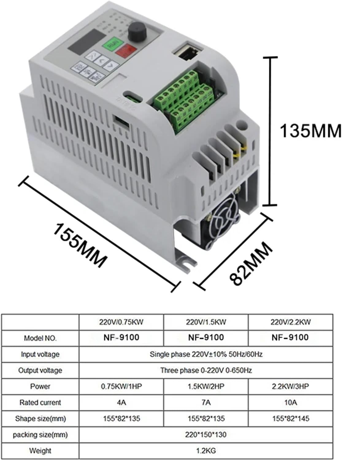
Figure 7.1: Dimensions for 0.75KW, 1.5KW, and 2.2KW models (approx. 155mm x 82mm x 135mm/145mm).

Figure 7.2: Dimensions for 4KW model (approx. 172mm x 125mm x 165mm).

Figure 7.3: Dimensions for 5.5KW model (approx. 220mm x 152mm x 179mm).

Figure 7.4: Dimensions for 7.5KW model (approx. 220mm x 152mm x 179mm).
8. Warranty and Support
For warranty information, technical support, or service inquiries, please contact your authorized QLWAHK distributor or reseller. Keep your purchase receipt as proof of purchase.