VEVOR 901-5500X
VEVOR 4kW Variable Frequency Drive User Manual
Model: 901-5500X (AT1-4000X)
1. Safety Information
Please read and understand all safety precautions before operating the VFD. Failure to comply may result in serious injury or property damage.
- Do not operate as requested, may cause death, severe injury or serious property loss.
- Before wiring, always make sure to cut off the power.
- Forbid to connect U/V/W output and to AC power supply, otherwise cause damage to the inverter.
- The inverter is forbidden to install on flammables, otherwise have the danger of fire.
- The ground terminal of the inverter must be grounded well.
- Do not install it in the environment with explosive gas, otherwise have the risk of explosion.
- Only professional people may carry on the wiring, converter internal has high pressure and prohibits secretly opening the shell.

Figure 1: Front view of the VFD showing the safety precautions label.
2. Product Overview
The VEVOR 4kW Variable Frequency Drive (VFD) is designed for precise motor speed control, offering stable performance and energy efficiency. It features a single-phase AC 220-240V input and a three-phase AC 220-240V output, with an adjustable output frequency range of 0-400 Hz.
Key features include:
- Superior Quality: 4kW, 18A, 5HP VFD for smooth motor start/stop and stable control.
- Easy Adjustment & Operation: Intuitive control panel with clear display and frequency knob. Removable panel for remote operation.
- Enhanced Safety & Durability: Equipped with a 10-layer protection system (overcurrent, overload, phase loss, etc.) and a triple-resistant PCB.
- Quiet & Efficient Power: Powerful cooling fan and multi-sided, multi-hole design for optimal ventilation and quiet operation.
- Versatile Application: Ideal for driving three-phase motors in various machinery such as compressors, lathes, fans, and milling machines.

Figure 2: The VFD is widely compatible with various 3-phase motors in industrial applications.
3. Specifications
| Parameter | Value |
|---|---|
| Model Number | AT1-4000X (901-5500X) |
| Power | 4 kW (5 HP) |
| Current | 18 A |
| Input Voltage | AC 220-240 V (Single-Phase) |
| Output Voltage | AC 220-240 V (Three-Phase) |
| Input Frequency | 50/60 Hz |
| Output Frequency | 0-400 Hz |
| Operating Temperature | 10°C-40°C (50°F-104°F) |
| Net Weight | 1.4 kg (3.1 lbs) ± 3% |
| Dimensions (L x W x H) | 11.81 x 22 x 14.15 cm (approx. 4.65 x 8.66 x 5.57 inches) |
| Mounting Type | Wall Mount |
| Certifications | CE |
| UPC | 197988846468 |

Figure 3: Visual representation of VFD dimensions and key specifications.
4. Setup and Installation
Proper installation is crucial for the safe and efficient operation of your VFD. Ensure all power is disconnected before proceeding with wiring.
4.1 Wiring Diagram
Connect the single-phase AC 220-240V input to the L and N terminals. Connect the three-phase motor to the U, V, and W output terminals. Ensure the ground terminal (GND) is properly connected to earth ground.

Figure 4: Wiring diagram for the VFD, showing input, output, and grounding connections.
4.2 Mounting
The VFD is designed for wall mounting. Choose a location that is dry, well-ventilated, and free from flammable materials or explosive gases. Ensure adequate clearance around the unit for proper heat dissipation.
5. Operation
The VFD features an intuitive control panel for easy parameter adjustment and operation.
5.1 Control Panel Overview

Figure 5: Detailed view of the VFD control panel.
- Status Indicator: Shows the current operational status.
- 5-Digit LED Display Screen: Displays frequency, parameters, and error codes.
- FWD/REV (Forward/Reverse Switching Key): Changes motor direction.
- DISP (Shift in Programming Mode, Jog in Normal Mode): Used for navigation and jogging.
- PROG (Selecting Mode or Programming Mode): Enters/exits programming mode.
- FUNC/DATA (Function Data Setting Key): Confirms parameter settings.
- Up/Down Arrows: Adjusts values and navigates menus.
- RUN (Start Inverter Output): Starts the motor.
- STOP/RESET (Break Down Fault Resetting): Stops the motor and resets faults.
- Speed Adjustment Knob: Fine-tunes the output frequency/motor speed.
5.2 Basic Operation Steps
- Ensure the VFD is correctly wired and powered on.
- Use the Speed Adjustment Knob to set the desired output frequency.
- Press the RUN button to start the motor.
- To stop the motor, press the STOP/RESET button.
- To change direction, press the FWD/REV button while the motor is stopped or running (depending on parameter settings).
5.3 Parameter Setting
Refer to the detailed parameter list in the included manual for advanced settings. Use the PROG, FUNC/DATA, and arrow keys to navigate and adjust parameters such as acceleration/deceleration times, maximum frequency, and motor parameters.
The removable panel with a 20 cm cable allows for convenient remote operation.
6. Maintenance
Regular maintenance ensures the longevity and optimal performance of your VFD.
- Cleaning: Keep the VFD clean and free from dust and debris. Use a soft, dry cloth for cleaning. Do not use liquid cleaners.
- Ventilation: Ensure the cooling fan and ventilation openings are not obstructed. The powerful fan is crucial for rapid cooling during prolonged use.
- Connections: Periodically check all wiring connections for tightness and signs of wear or corrosion.
- Environment: Maintain the operating environment within the specified temperature and humidity ranges.
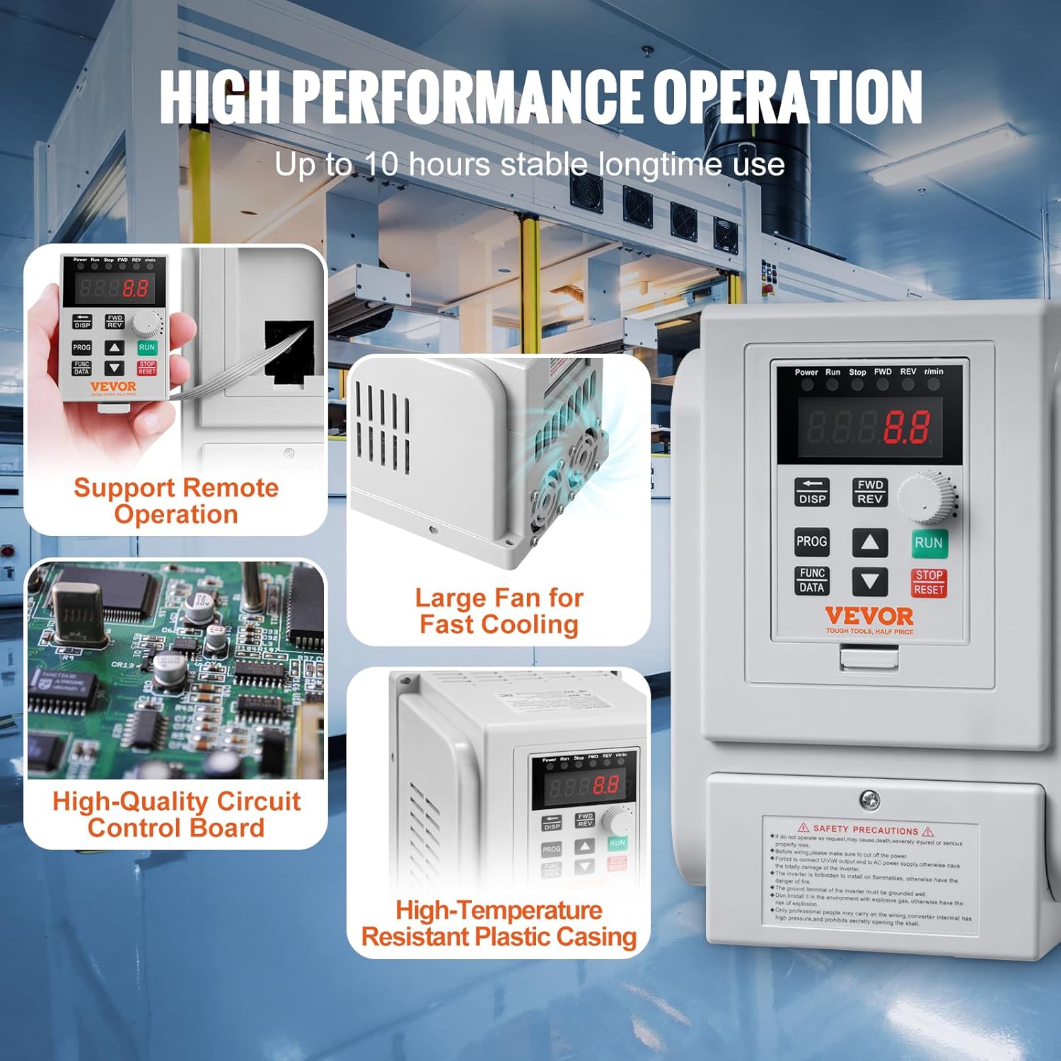
Figure 6: Internal view highlighting the large fan for fast cooling and high-quality circuit control board.
7. Troubleshooting
The VFD is equipped with a 10-layer multiple protection system to safeguard against various faults. If an error occurs, the display will show a corresponding error code.

Figure 7: Overview of the VFD's 10-level multiple protection system.
Common Protection Features:
- Overcurrent Protection
- Overvoltage Protection
- Overheat Protection
- Reverse Power Protection
- Ground Short Circuit Protection
- Input Phase-Loss Protection
- Output Phase-Loss Protection
- Load Overload 100% Protection
- Load Overload 150% Protection
- Inverter Overload 150% Protection
General Troubleshooting Steps:
- Identify Error Code: Note any error codes displayed on the LED screen. Refer to the full manual for specific error code meanings.
- Power Cycle: Turn off the VFD, wait a few minutes, and then turn it back on.
- Check Connections: Verify all power and motor connections are secure and correct.
- Check Load: Ensure the motor load is within the VFD's specifications. For higher motor loads, a more powerful VFD may be required.
- Ventilation: Confirm that the VFD's cooling fan is operating and not obstructed.
- Reset Fault: After resolving the issue, press the STOP/RESET button to clear the fault.
If the problem persists, contact VEVOR customer support for assistance.
8. Warranty and Support
VEVOR is committed to providing high-quality products and excellent customer service.
For any inquiries, technical support, or warranty claims, please contact VEVOR customer service. VEVOR offers attentive 24/7 support to assist you with your product.
Please retain your purchase receipt for warranty purposes.
Ask a question about this manual
Ask about setup, troubleshooting, compatibility, parts, safety, or missing instructions. Manuals+ will review the question and use this page’s manual context to help answer it.